Jeep Parts Wiki | Ford Parts Wiki
Home | Search | Browse
|
Body Service Manual August 1964 |
|
Prev

 Next
Next
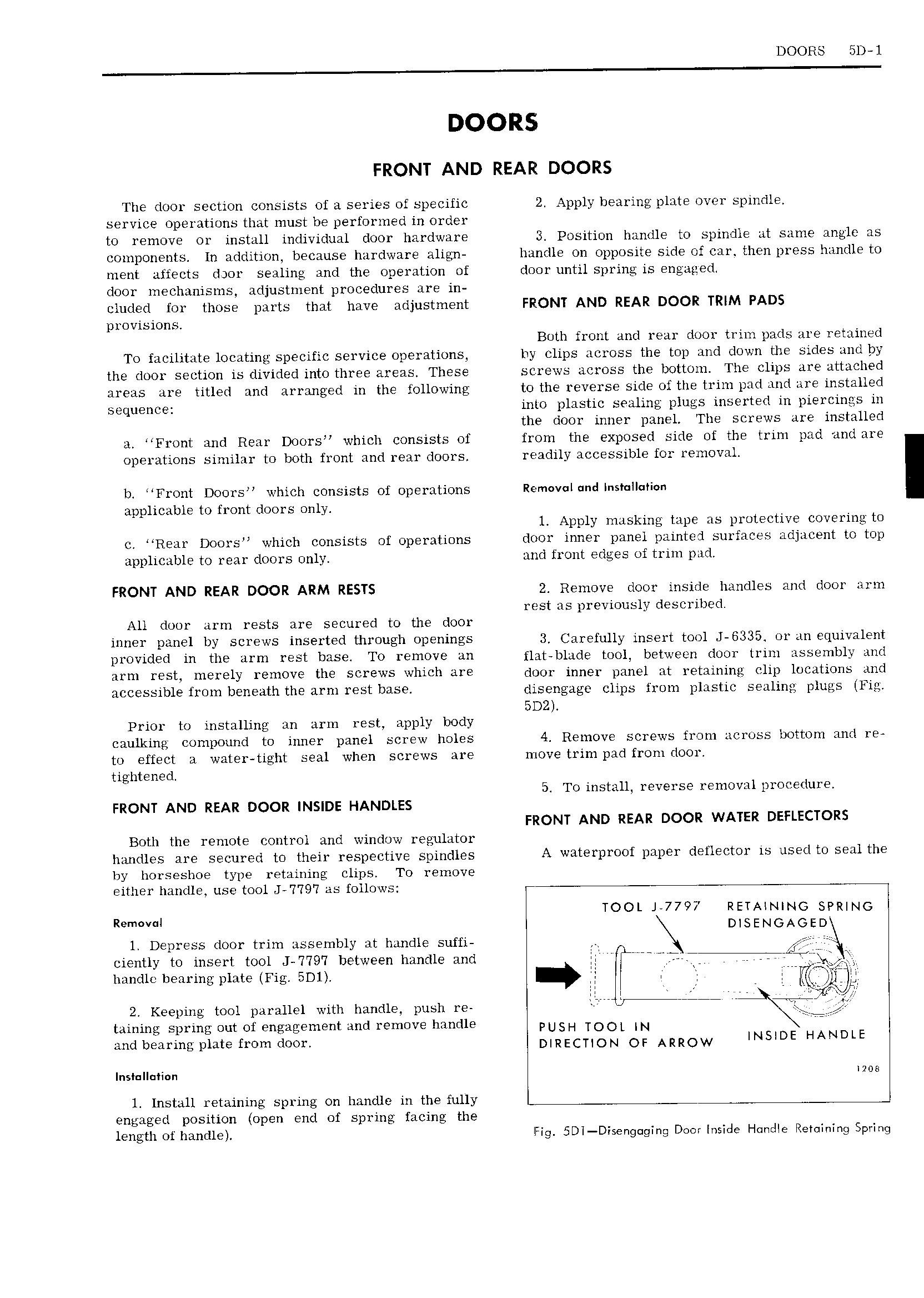
DOORS 5D l DOORS FRONT AND REAR DOORS The door section consists of a series of specific 2 Apply bearing plate over spindle service operations that must be performed in order to remove or install individual door hardware 3 Position handle to spindle at same angle as components ln addition because hardware align handle on opposite side of car then press handle to ment affects dyor sealing and the operation of door until spring is engaged door mechanisms adjustment procedures are in eluded for those parts that have adjustment FRONT AND REAR DOOR TRIM PADS provisions Both front and rear door trim pads are retained To facilitate locating specific service operations by clips across the top and down the sides and by the door section is divided into three areas These screws across the bottom The clips are attached areas are titled and arranged in the following to the reverse side of the trim pad and are installed sequence into plastic sealing plugs inserted in piercings in the door inner panel The screws are installed a Front and Rear Doors which consists of from the exposed side of the trim pad and are operations similar to both front and rear doors readily accessible for removal Ii Front Doors which consists of operations Re m v l nd I s lI i applicable to front doors only 1 Apply masking tape as protective covering to c Rear Doors which consists of operations door inner panel paintel surfaces adjacent to top applicable to rear doors only and front edges of trim pad FRONT AND REAR DOOR ARM RESTS 2 Remove door inside handles and door arm rest as previously described All door arm rests are secured to the door inner panel by screws inserted through openings 3 Carefully insert tool J 6335 or an equivalent Dl 0Vi l fI IH UIQ iifm l St IJHSG T0 l H10V 1111 flat blade tool between door trim assembly and HPD f 5I IHGYBIY l 9m0V thi SGFGWS which LWB door inner panel at retaining clip locations and accessible from beneath the arm rest base qiisengage glipg from plastic segljjjg plugs Fig 5D2I Prior to installing an arm rest apply body caulking compound to inner panel screw holes 4 Remove screws from across bottom and re to effect a water tight seal when screws are move trim pad from door tightened 5 To install reverse removal procedure FRONT AND REAR DOOR INSIDE HANDLES FRONT AND REAR DOOR WATER DEFLECTORS Botti the remote control and window regulator handles are secured to their respective spindles A waterproof paper deflector is used to seal the by horseshoe type retaining clips To remove either handle use tool J 7 79 7 as follows 4 Removal TOOL JV7797 RETAINING SPRING DISENGAGED 1 Depress door trim assembly at handle suffi ciently to insert tool J 7 79 7 between handle and L i1 e rfy handle bearing plate Fig 5Dl I II 1 r I Wgii B K 2 Keeping tool parallel with handle push re err taining spring out of engagement and remove handle PUSH TOOT IN and bearing plate from door DIRECTION OI ARROW INSIDE HANDLE Inslulluiion noe l Install retaining spring on handle in the fully engaged position open end of spring facing the length of handle tig 5DI Disenguging Door Inside Hnndle Retaining Spring

 Next
Next