Jeep Parts Wiki | Ford Parts Wiki
Home | Search | Browse
|
Body Service Manual August 1964 |
|
Prev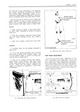

 Next
Next
5D l6 DOORS r Carefully pry clips from slots in panel and FRONT AND REAR UP remove strip assembly TRAVEL STOP SCREWS 5 To install position strip assembly so that x V all clip tangs start into slots in door panel then A n i lr press at each clip location and engage clips I i LOWER SAS I FRONT GUIDE lOW ER V CHANNEL CAM prior to installing strip assembly reform clip ADJUSTING r tangs to assure positive retention when installed gg REAR SCREW swo NUTM 4 r 1 NOTE To make strip assembly removal tool l if make a l 4 wide by 3 8 deep slot in a J 2772 hendlining inserting tool or equivalent INNER PANEL va QAM 5gR5w5 REAR GUIDE LOWER ADIUSTING STUD NUT REAR DOOR WINDOW ASSEMBLY The rear door window assembly consists of a Fl9 5D25 R T DMT H TdW T solid tempered safety plate glass window and a bolted on lower sash channel With this design the door glass and sash channel are removed from LOWER A H CHANNEL CAM the door as a unit and glass replacements made in bench operations Figure 5D2 I is an exploded R d 5 T view of the rear door window assembly and iden tifies the various components and their assembly 1 Ringove rear door trim pan and inner panel sequence When assembling window do not torque waterte ec or sash channel nuts in excess of 50 inch pounds 4 foot pounds Also replace glass to sash channel 2 Lower door window and remove lower sash SDaCB1 S channel cam front attaching screw through lower front access hole Fig 5D24 CAUTION Use care to make certain that glass does not strike hard objects Edge chips or 3 Operate window up and remove sash channel deep scratches can cause solid tempered safety cam rear attaching screw through large access plate glass to shatter Do not attempt to drill hole Fig 51325 or grind glass 4 Supporting window with one hand disengage REm v I nd ns G l i n sash channel cam from window lower sash channel fm lt tY 1 1 i liter thm cm 1 Remove Wrnrinw inwer sash einnnei cam ana dm UWB mmml U Om U Om both inner and outer glass run channel strip as ll 1 l b I 5 To install reverse removal procedure hem 1 ih pwvmub Y CEBCU H 2 Loosen attaching screws for both front and GLASS HA i 1 E ii 2 I l D S 45 INNER AND OUTER STRIP ASSEMBLIES D Pd tr Remcvnl nnd Ins lI va n 1 Remove door window lower sash channel cam ll as previously described 2 Remove screws at front and rear of strip A assembly railgy wir L 1 7 T w 1 a w 3 Apply cloth backed tape as protective cover to y r r painted surfaces adjacent to strip assembly ies to be removed 4 Insert a flat blade tool that is slotted to fit Wi over tang of clip between door panel return flange and strip assembly at clip locations Fig 5D28 Fig 5D26 D r Inner or Outer Strip Removal