Jeep Parts Wiki | Ford Parts Wiki
Home | Search | Browse
|
Body Service Manual August 1964 |
|
Prev
 Next
Next
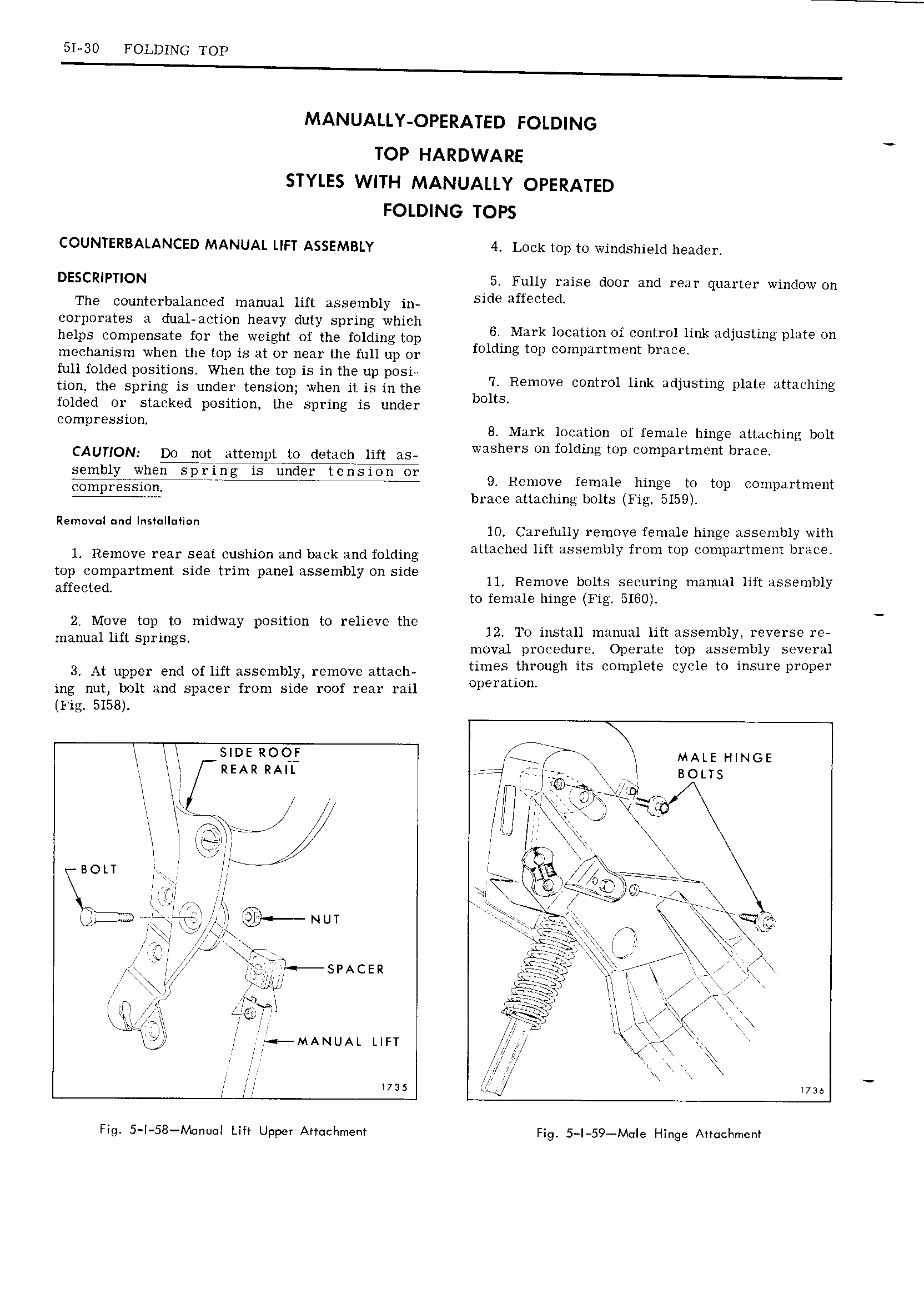
51 30 FOLDING TOP MANUALLY OPERATED FOLDING TOP HARDWARE STYLES WITH MANUALLY OPERATED FOLDING TOPS COUNTERBALANCED MANUAL LIFT ASSEMBLY 4 Lock top to windshield header DESCRIPTION 5 Fully raise door and rear quarter window on The counterbalanced manual lift assembly in Side afmcted corporates a dual action heavy duty spring which A I I helps compensate for the weight of the folding top f 16 I k1 Ci tiol hm dJ g DLHG On mechanism when the top is at or near the full up or O mg mp Compu men 3 me full folded positions When the top is in the up posi 4 V J M tion the Spring is under tensmni when it is in the b Remove contiol link adjusting plate attathing folded or stacked position the spring is under 0 S compression 8 Mark location of female hinge attaching bolt CAUTION DO QQ Mtelnptrjo detach hit s washers on folding top compartment brace r iV I3g 9 Remove female hinge to top compartment 4 brace attaching bolts Fig 5159 Removal und Insmllmion 10 Carefully remove female hinge assembly with lb Remove mar Seat cushion and back and folding attached lift assembly from top compartment brace tz coglpartment Side trim panel assembly On side ll Remove bolts securing manual lift assembly a Ecte to female hinge Fig 5160 2 F Ogg mp to midway position to relieve mg 12 To install manual lift assembly reverse re mamm 1 Springs moval procedure Operate top assembly several 3 At upper end of lift assembly remove attach tune tllnough ith complete we G to msme propel ing nut bolt and spacer from side roof rear rail Opera wu Fig 5158 I N suns ROOF I MALE HINGE I REAR RAIL r I y T j I BOLTS I I I Itiie zi I II III I I It w I rt I I l N I M Ii I IQILILFLFVJ I le X I I I I I A N I I I E fi J 9 tig ii p W i GI yy jT LII I at i V I I II Nur e K F Y IPI I I bx I It 7 gi TT sI Ace r Q I I M II te I s Si II I I FI I k i II I WI Tw I II 7 MANUAL LIFT fl r em Il was i V l was Fig 5 I 58 Manual Lift Upper Attachment Fig 5 I 59 M Ie Hinge Attachment