Jeep Parts Wiki | Ford Parts Wiki
Home | Search | Browse
Prev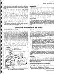
 Next
Next
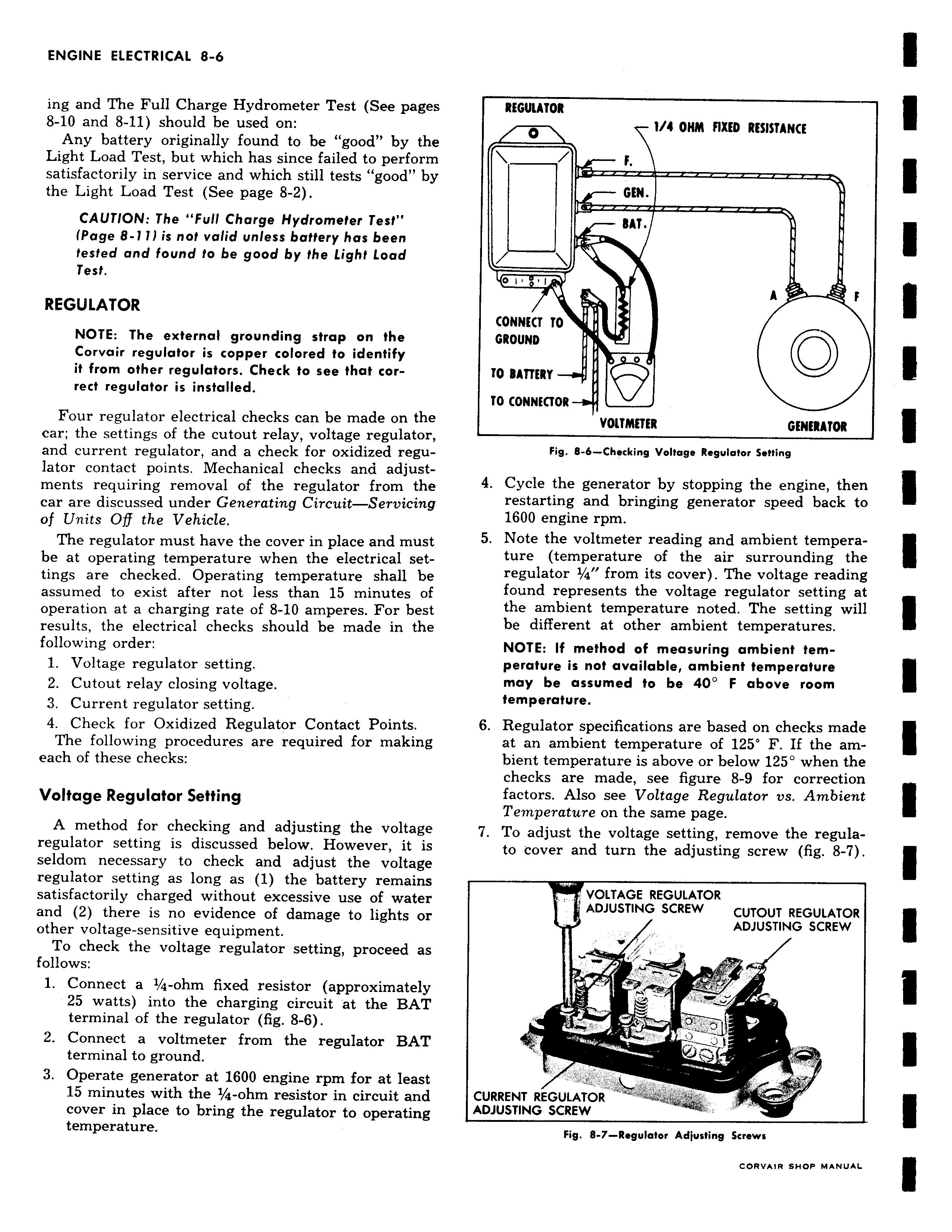
ing and The Full Charge Hydrometer Test See pages 8 10 and 8 11 should be used on Any battery originally found to be good by the Light Load Test but which has since failed to perform satisfactorily in service and which still tests good by the Light Load Test See page 8 2 CAUTION The Full Charge Hydrometer Test Page 8 111 is not valid unless battery has been tested and found to be good by the Light Load Test REGULATOR NOTE The external grounding strap on the Corvair regulator is copper colored to identify it from other regulators Check to see that correct regulator is installed Four regulator electrical checks can be made on the car the settings of the cutout relay voltage regulator and current regulator and a check for oxidized regulator contact points Mechanical checks and adjustments requiring removal of the regulator from the car are discussed under Generating Circuit Servicing of Units Of the Vehicle The regulator must have the cover in place and must be at operating temperature when the electrical settings are checked Operating temperature shall be assumed to exist after not less than 15 minutes of operation at a charging rate of 8 10 amperes For best results the electrical checks should be made in the following order 1 Voltage regulator setting 2 Cutout relay closing voltage 3 Current regulator setting 4 Check for Oxidized Regulator Contact Points The following procedures are required for making each of these checks Voltage Regulator Setting A method for checking and adjusting the voltage regulator setting is discussed below However it is seldom necessary to check and adjust the voltage regulator setting as long as 1 the battery remains satisfactorily charged without excessive use of water and 2 there is no evidence of damage to lights or other voltage sensitive equipment To check the voltage regulator setting proceed as follows 1 Connect a 1 4 ohm fixed resistor approximately 25 watts into the charging circuit at the BAT terminal of the regulator fig 8 6 2 Connect a voltmeter from the regulator BAT terminal to ground 3 Operate generator at 1600 engine rpm for at least 15 minutes with the 1 4 ohm resistor in circuit and cover in place to bring the regulator to operating temperature REGULATOR 1 4 OHM FIXED RESISTANCE f GEN BAT i A i CONNECT TO GROUND 0 i0 BATTERY 00 TO CONNECTOR VOLTMETER GENERATOR Fig 8 6 Checking Voltage Regulator Setting 4 Cycle the generator by stopping the engine then restarting and bringing generator speed back to 1600 engine rpm 5 Note the voltmeter reading and ambient temperature temperature of the air surrounding the regulator r 4 from its cover The voltage reading found represents the voltage regulator setting at the ambient temperature noted The setting will be different at other ambient temperatures NOTE If method of measuring ambient temperature is not available ambient temperature may be assumed to be 40 F above room temperature 6 Regulator specifications are based on checks made at an ambient temperature of 125 F If the ambient temperature is above or below 125 when the checks are made see figure 8 9 for correction factors Also see Voltage Regulator vs Ambient Temperature on the same page 7 To adjust the voltage setting remove the regulato cover and turn the adjusting screw fig 8 7 VOLTAGE REGULATOR ADJUSTING SCREW CUTOUT REGULATOR ADJUSTING SCREW r J w CURRENT REGULATOR ADJUSTING SCREW Fig 8 7 Regulator Adjusting Screws