Jeep Parts Wiki | Ford Parts Wiki
Home | Search | Browse | Marketplace | Messages | FAQ | Guest
Prev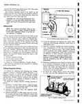

 Next
Next
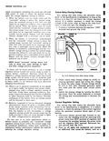
Increase spring tension to raise the setting decrease spring tension to lower the setting CAUTION Final adjustment should always be made by increasing spring tension to assure contact between the screw head and spring support Sometimes the spring support does not follow the screw head as spring tension is decreased and it will be necessary to bend the spring support up to insure contact between the spring support and screw head before final adjustment is completed fig 8 8 Failure of the voltage regulator unit to hold its setting usually results from 1 setting or checking the voltage regulator at other than operating temperature and 2 the screw head not touching the spring support after final udjustment is complete Before taking the reading after each adjustment replace the regulator cover as quickly as possible and cycle the generator SPRING SUPPORT i ADJUSTING SCREW Y SCREW HEAD MUST TOUCH SUPPORT AT THIS POINT AFTER FINAL ADJUSTMENT Fig 8 8 Confa t Between Regulator Spring Support and Adjusting Screw Voltage Regulator vs Ambient Temperature The voltage regulator Normal Range setting specifications described in this section refer to a regulator which has been brought to a stabilized operating temperature at an ambient temperature of 125 F Ambient temperature is the temperatun of the air surrounding the regulator approximately Y4 of an inch from the regulator cover Since the stabilized operating temperature of the regulator varies with the ambient temperature the voltage regulator Normal Range setting varies accordingly Fig Lire 8 9 illustrates the normal range settings at various ambient temperatures and how the voltage regulator setting varies at different ambient temperatures as indicated by the vertical line Through the use of the table in Figure 8 9 it is possible to determine correct voltage readings at any ambient temperature from 45 to 165 F STANDARD REGULATOR VOLTAGE REGULATOR SPECIFICATIONS vS REGULATOR AMBIENT TEMPERATURE REGULATOR VOLTAGE TEMPERATURE LOW HIGH 165 F 13 1 13 9 1450 F 13 5 14 3 125 F laft 2 1050 F 14 0 14 9 5 F 14 2 15 2 65 F 14 4 15 4 45 F 14 5 15 6 SPECIFIC I e L RANGE INDICATES PUBLISHED SPECIFICATIONS Fig 8 9 Voltage Regulator Correction Factors When the corrected voltage regulator setting falls within the normal range given in the specifications and the battery condition has been satisfactory after a reasonable period of operation with this setting the regulator setting should not be disturbed When the corrected voltage regulator setting falls inside or outside the normal range given in the specifications but battery condition has been unsatisfactory after a reasonable period of operation with this setting tailor the voltage regulator setting as described under Tailoring the Voltage Regulator Setting below Tailoring the Voltage Regulator Setting The desired voltage regulator setting is that which keeps the battery in a satisfactory state of charge without causing excessive water usage as evidenced by