Jeep Parts Wiki | Ford Parts Wiki
Home | Search | Browse | Marketplace | Messages | FAQ | Guest
Prev
 Next
Next
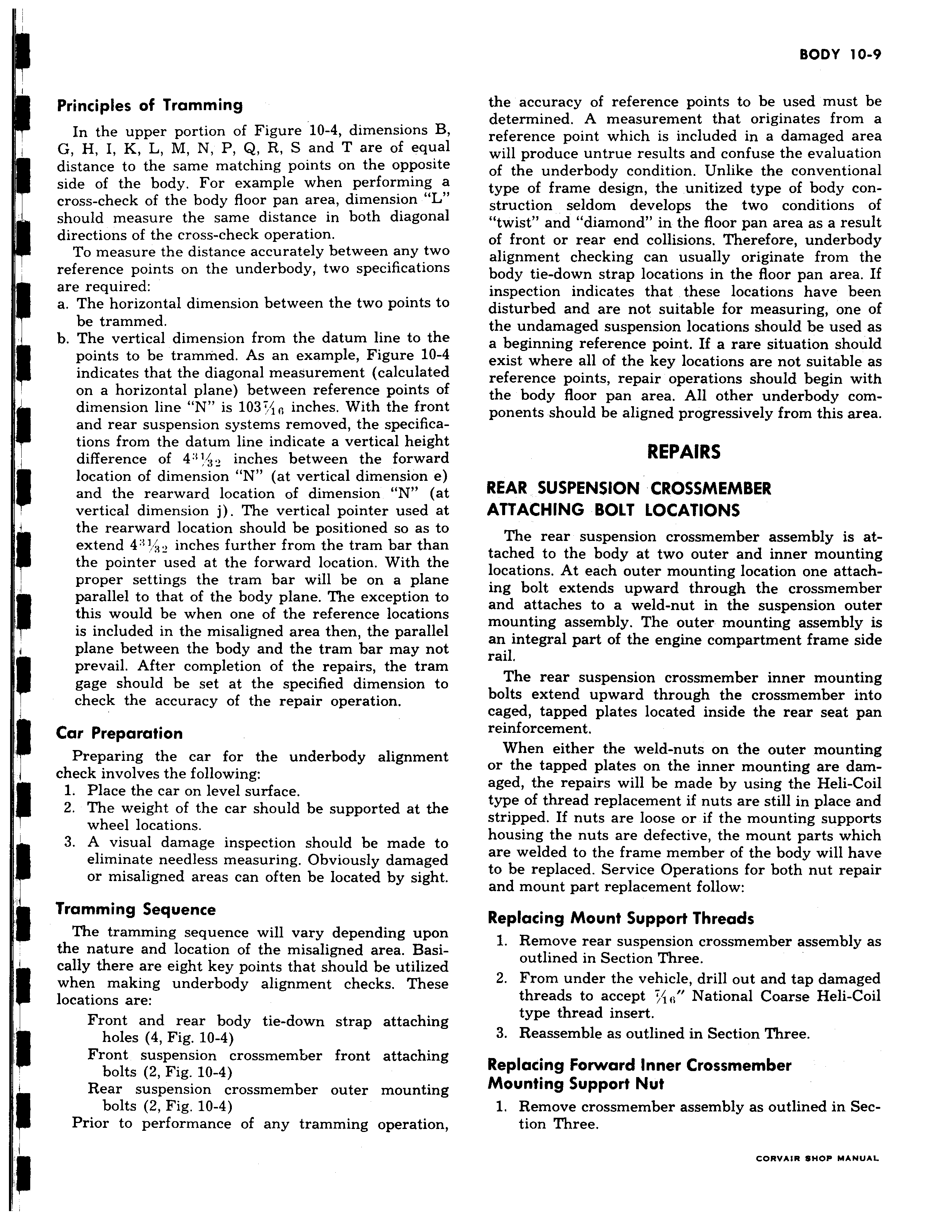
Principles of Tramming In the upper portion of Figure 10 4 dimensions B G H I K L M N P Q R S and T are of equal distance to the same matching points on the opposite side of the body For example when performing a cross check of the body floor pan area dimension L should measure the same distance in both diagonal directions of the cross check operation To measure the distance accurately between any two reference points on the underbody two specifications are required a The horizontal dimension between the two points to be trammed b The vertical dimension from the datum line to the points to be trammed As an example Figure 10 4 indicates that the diagonal measurement calculated on a horizontal plane between reference points of dimension line N is 103 inches With the front and rear suspension systems removed the specifications from the datum line indicate a vertical height difference of 4 3 inches between the forward location of dimension N at vertical dimension e and the rearward location of dimension N at vertical dimension j The vertical pointer used at the rearward location should be positioned so as to extend 4B i inches further from the tram bar than the pointer used at the forward location With the proper settings the tram bar will be on a plane r parallel to that of the body plane The exception to this would be when one of the reference locations is included in the misaligned area then the parallel plane between the body and the tram bar may not prevail After completion of the repairs the tram gage should be set at the specified dimension to check the accuracy of the repair operation Car Preparation Preparing the car for the underbody alignment check involves the following 1 Place the car on level surface 2 The weight of the car should be supported at the wheel locations I 3 A visual damage inspection should be made to eliminate needless measuring Obviously damaged or misaligned areas can often be located by sight Tramming Sequence The tramming sequence will vary depending upon the nature and location of the misaligned area Basically there are eight key points that should be utilized when making underbody alignment checks These locations are Front and rear body tie down strap attaching holes 4 Fig 10 4 Front suspension crossmember front attaching bolts 2 Fig 10 4 Rear suspension crossmember outer mounting bolts 2 Fig 10 4 Prior to performance of any tramming operation r the accuracy of reference points to be used must be determined A measurement that originates from a reference point which is included in a damaged area will produce untrue results and confuse the evaluation of the underbody condition Unlike the conventional type of frame design the unitized type of body construction seldom develops the two conditions of twist and diamond in the floor pan area as a result of front or rear end collisions Therefore underbody alignment checking can usually originate from the body tie down strap locations in the floor pan area If inspection indicates that these locations have been disturbed and are not suitable for measuring one of the undamaged suspension locations should be used as a beginning reference point If a rare situation should exist where all of the key locations are not suitable as reference points repair operations should begin with the body floor pan area All other underbody components should be aligned progressively from this area REPAIRS REAR SUSPENSION CROSSMEMBER ATTACHING BOLT LOCATIONS The rear suspension crossmember assembly is attached to the body at two outer and inner mounting locations At each outer mounting location one attaching bolt extends upward through the crossmember and attaches to a weld nut in the suspension outer mounting assembly The outer mounting assembly is an integral part of the engine compartment frame side rail The rear suspension crossmember inner mounting bolts extend upward through the crossmember into caged tapped plates located inside the rear seat pan reinforcement When either the weld nuts on the outer mounting or the tapped plates on the inner mounting are damaged the repairs will be made by using the Heli Coil type of thread replacement if nuts are still in place and stripped If nuts are loose or if the mounting supports housing the nuts are defective the mount parts which are welded to the frame member of the body will have to be replaced Service Operations for both nut repair and mount part replacement follow Replacing Mount Support Threads 1 Remove rear suspension crossmember assembly as outlined in Section Three 2 From under the vehicle drill out and tap damaged threads to accept 1 National Coarse Heli Coil type thread insert 3 Reassemble as outlined in Section Three Replacing Forward Inner Crossmember Mounting Support Nut 1 Remove crossmember assembly as outlined in Section Three CORVAIR SHOP MANUAL