Jeep Parts Wiki | Ford Parts Wiki
Home | Search | Browse
Prev

 Next
Next
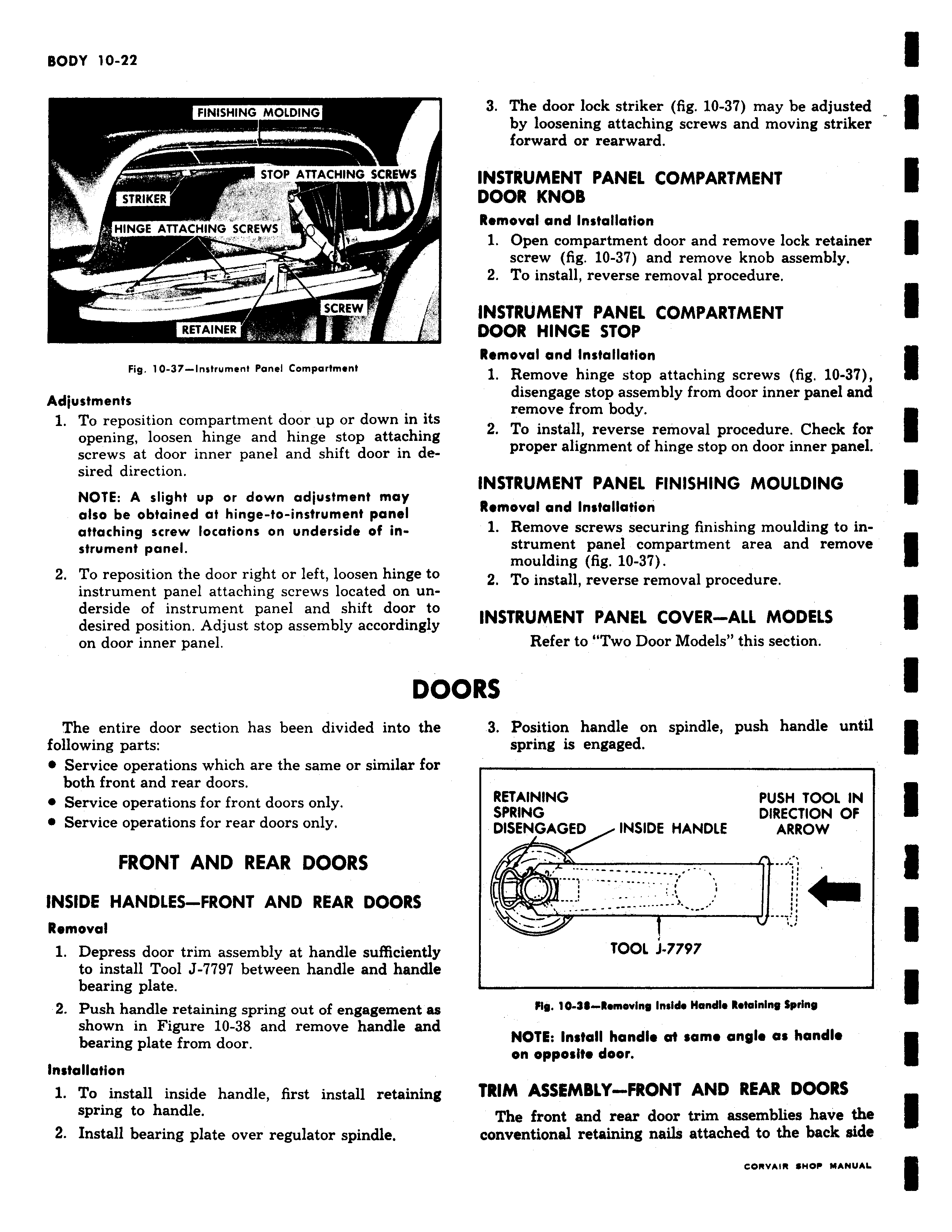
FINISHING MOLDING w W rrrrr STOP ATTACHING SCREWS STRIKER w HINGE ATTACHING SCREWS w M RETAINER Fig 10 37 Instrument Panel Comportment Adjustments 1 To reposition compartment door up or down in its opening loosen hinge and hinge stop attaching screws at door inner panel and shift door in desired direction NOTE A slight up or down adjustment may also be obtained at hinge to instrument panel attaching screw locations on underside of instrument panel 2 To reposition the door right or left loosen hinge to instrument panel attaching screws located on underside of instrument panel and shift door to desired position Adjust stop assembly accordingly on door inner panel DO The entire door section has been divided into the following parts e Service operations which are the same or similar for both front and rear doors e Service operations for front doors only e Service operations for rear doors only FRONT AND REAR DOORS INSIDE HANDLES FRONT AND REAR DOORS Removal 1 Depress door trim assembly at handle sufficiently to install Tool J 7797 between handle and handle bearing plate 2 Push handle retaining spring out of engagement as shown in Figure 10 38 and remove handle and bearing plate from door Installation 1 To install inside handle first install retaining spring to handle 2 Install bearing plate over regulator spindle 3 The door lock striker fig 10 37 may be adjusted by loosening attaching screws and moving striker forward or rearward INSTRUMENT PANEL COMPARTMENT DOOR KNOB Removal and Installation 1 Open compartment door and remove lock retainer screw fig 10 37 and remove knob assembly 2 To install reverse removal procedure INSTRUMENT PANEL COMPARTMENT DOOR HINGE STOP Removal and Installation 1 Remove hinge stop attaching screws fig 10 3 disengage stop assembly from door inner panel and remove from body 2 To install reverse removal procedure Check for proper alignment of hinge stop on door inner panel INSTRUMENT PANEL FINISHING MOULDING Removal and Installation 1 Remove screws securing finishing moulding to instrument panel compartment area and remove moulding fig 10 37 2 To install reverse removal procedure INSTRUMENT PANEL COVER ALL MODELS Refer to Two Door Models this section DRS 3 Position handle on spindle push handle until spring is engaged RETAINING PUSH TOOL IN SPRING DIRECTION OF DISENGAGED INSIDE HANDLE ARROW TOOL J 7797 Fig 10 9 Ronsoviny Inside Handle Retaining Spring NOTE Install handle a1 some angle as handle on opposite door TRIM ASSEMBLY FRONT AND REAR DOORS The front and rear door trim assemblies have the conventional retaining nails attached to the back side

 Next
Next