Jeep Parts Wiki | Ford Parts Wiki
Home | Search | Browse | Marketplace | Messages | FAQ | Guest
Prev

 Next
Next
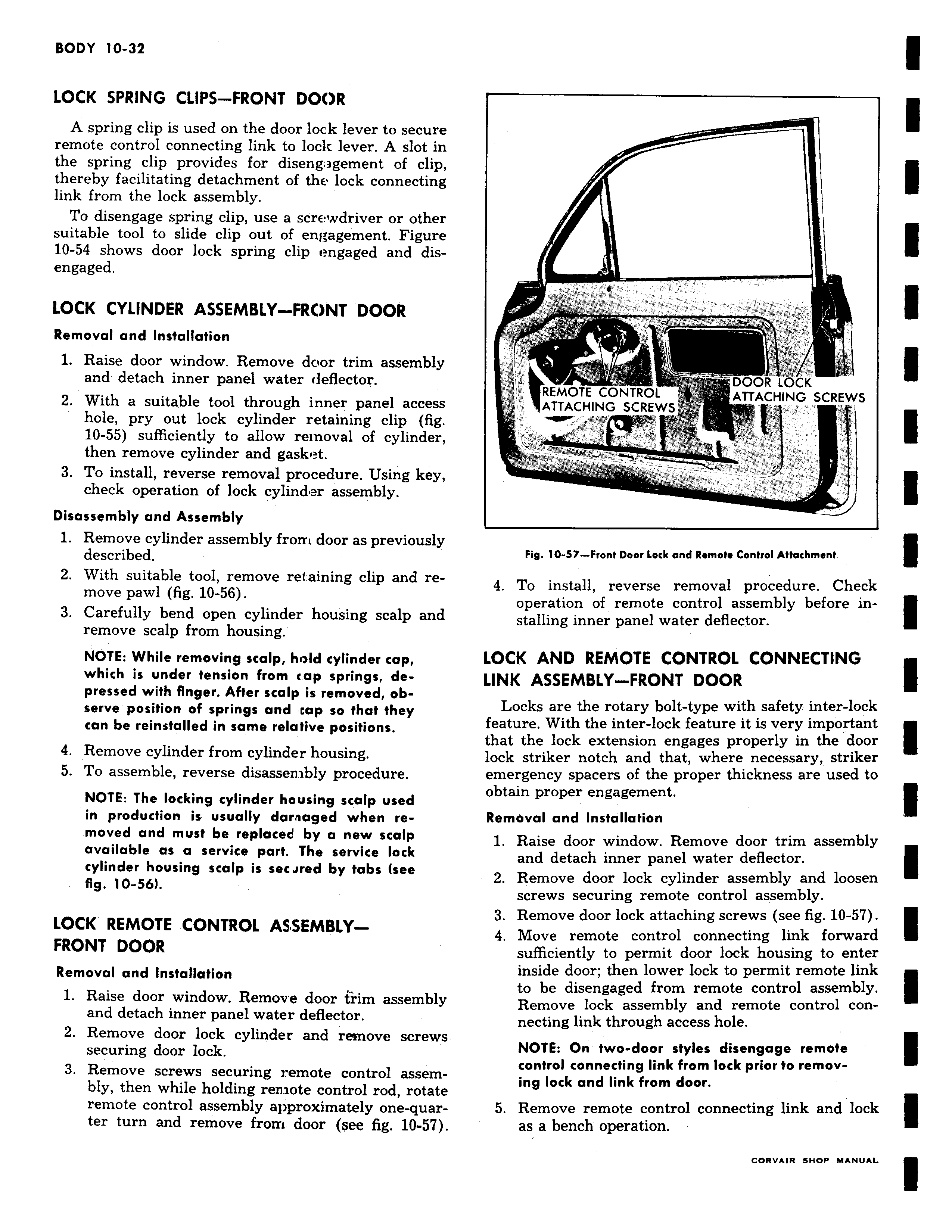
LOCK SPRING CLIPS FRONT DOOR A spring clip is used on the door lock lever to secure remote control connecting link to lock lever A slot in the spring clip provides for disengagement of clip thereby facilitating detachment of the lock connecting link from the lock assembly To disengage spring clip use a screwdriver or other suitable tool to slide clip out of engagement Figure 10 54 shows door lock spring clip engaged and disengaged LOCK CYLINDER ASSEMBLY FRONT DOOR Removal and Installation 1 Raise door window Remove door trim assembly and detach inner panel water deflector 2 With a suitable tool through inner panel access hole pry out lock cylinder retaining clip fig 10 55 sufficiently to allow removal of cylinder then remove cylinder and gasket 3 To install reverse removal procedure Using key check operation of lock cylinder assembly Disassembly and Assembly 1 Remove cylinder assembly from door as previously described 2 With suitable tool remove retaining clip and remove pawl fig 10 56 3 Carefully bend open cylinder housing scalp and remove scalp from housing NOTE While removing scalp hold cylinder cap which is under tension from cap springs depressed with finger After scalp is removed observe position of springs and cap so that they can be reinstalled in same relative positions 4 Remove cylinder from cylinder housing 5 To assemble reverse disassen ibly procedure NOTE The locking cylinder housing scalp used in production is usually darnaged when re moved and must be replaced by a new scalp available as a service part The service lock cylinder housing scalp is secrred by tabs see fig 10 56 LOCK REMOTE CONTROL ASSEMBLYFRONT DOOR Removal and Installation 1 Raise door window Remove door trim assembly and detach inner panel water deflector 2 Remove door lock cylinder and remove screws securing door lock 3 Remove screws securing remote control assembly then while holding remote control rod rotate remote control assembly approximately one quar ter turn and remove from door see fig 10 57 ly II v DOOR LOCK REMOTE CONTROL ATTACHING SCREWS ATTACHING SCREWS k 3 I Fig 10 57 Front Door Lock and Remote Control Attachment 4 To install reverse removal procedure Check operation of remote control assembly before installing inner panel water deflector LOCK AND REMOTE CONTROL CONNECTING LINK ASSEMBLY FRONT DOOR Locks are the rotary bolt type with safety inter lock feature With the inter lock feature it is very important that the lock extension engages properly in the door lock striker notch and that where necessary striker emergency spacers of the proper thickness are used to obtain proper engagement Removal and Installation 1 Raise door window Remove door trim assembly and detach inner panel water deflector 2 Remove door lock cylinder assembly and loosen screws securing remote control assembly 3 Remove door lock attaching screws see fig 10 57 4 Move remote control connecting link forward sufficiently to permit door lock housing to enter inside door then lower lock to permit remote link to be disengaged from remote control assembly Remove lock assembly and remote control connecting link through access hole NOTE On two door styles disengage remote control connecting link from lock prior to removing lock and link from door 5 Remove remote control connecting link and lock as a bench operation

 Next
Next