Jeep Parts Wiki | Ford Parts Wiki
Home | Search | Browse
Prev
 Next
Next
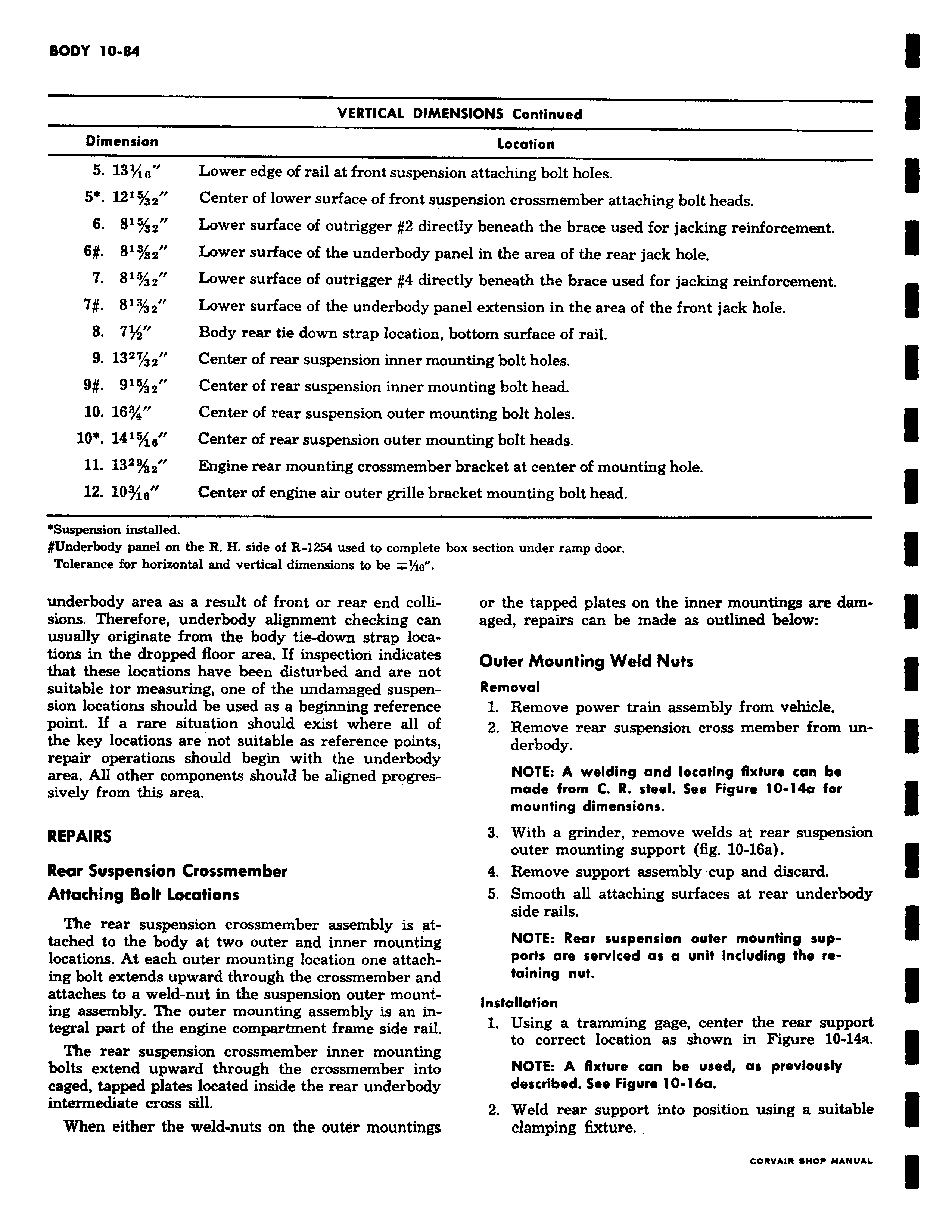
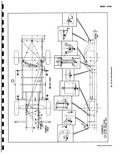
VERTICAL DIMEI Dimension 5 13 ig Lower edge of rail at front suspensic 5 1215 32 Center of lower surface of front sus 6 815 s2 Lower surface of outrigger 2 direc g 81 2 Lower surface of the underbody pai 7 81 2 f Lower surface of outrigger 4 direc 7 813 32 Lower surface of the underbody pai 8 7 Body rear tie down strap location 1 9 13z7 32 Center of rear suspension inner mot 9 915 32 Center of rear suspension inner mot 10 163 Center of rear suspension outer moi 10 141 o Center of rear suspension outer mot 11 132 z Engine rear mounting crossmember 12 103 ig Center of engine air outer grille bra Suspension installed Underbody panel on the R H side of R 1254 used to complete b Tolerance for horizontal and vertical dimensions to be s underbody area as a result of front or rear end collisions Therefore underbody alignment checking can usually originate from the body tie down strap locations in the dropped floor area If inspection indicates that these locations have been disturbed and are not suitable ior measuring one of the undamaged suspension locations should be used as a beginning reference point If a rare situation should exist where all of the key locations are not suitable as reference points repair operations should begin with the underbody area All other components should be aligned progressively from this area REPAIRS Rear Suspension Crossmember Attaching Bolt Locations The rear suspension crossmember assembly is attached to the body at two outer and inner mounting locations At each outer mounting location one attaching bolt extends upward through the crossmember and attaches to a weld nut in the suspension outer mounting assembly The outer mounting assembly is an integral part of the engine compartment frame side rail The rear suspension crossmember inner mounting bolts extend upward through the crossmember into caged tapped plates located inside the rear underbody intermediate cross sill When either the weld nuts on the outer mountings JSIONS Continued Location in attaching bolt holes 3ension crossmember attaching bolt heads tly beneath the brace used for jacking reinforcement zel in the area of the rear jack hole tly beneath the brace used for jacking reinforcement iel extension in the area of the front jack hole iottom surface of rail mting bolt holes mting bolt head mting bolt holes nting bolt heads bracket at center of mounting hole ket mounting bolt head m section under ramp door or the tapped plates on the inner mountings are damaged repairs can be made as outlined below Outer Mounting Weld Nuts Removal 1 Remove power train assembly from vehicle 2 Remove rear suspension cross member from underbody NOTE A welding and locating fixture can be made from C R steel See Figure 10 14a far mounting dimensions 3 With a grinder remove welds at rear suspension outer mounting support fig 10 16a 4 Remove support assembly cup and discard 5 Smooth all attaching surfaces at rear underbody side rails NOTE Rear suspension outer mounting supports are serviced as a unit including the retaining nut Installation 1 Using a tramming gage center the rear support to correct location as shown in Figure 10 14a NOTE A fixture can be used as previously described See Figure 10 16a 2 Weld rear support into position using a suitable clamping fixture