Jeep Parts Wiki | Ford Parts Wiki
Home | Search | Browse
Prev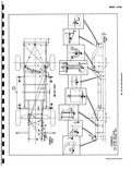
 Next
Next
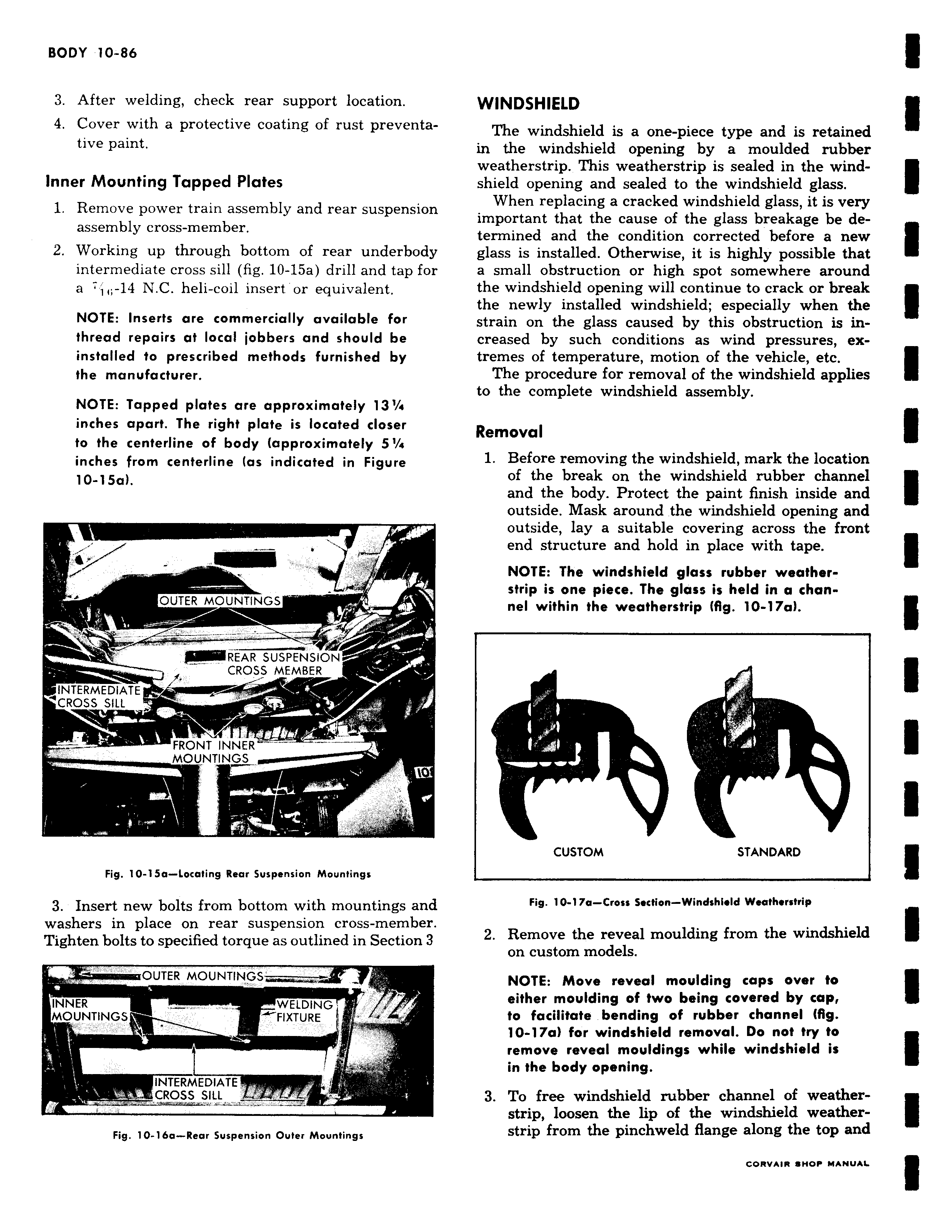
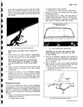
3 After welding check rear support location 4 Cover with a protective coating of rust preventative paint Inner Mounting Tapped Plates 1 Remove power train assembly and rear suspension assembly cross member 2 Working up through bottom of rear underbody intermediate cross sill fig 10 15a drill and tap for a 7 1 14 N C heli coil insert or equivalent NOTE Inserts are commercially available for thread repairs at local jobbers and should be installed to prescribed methods furnished by the manufacturer NOTE Tapped plates are approximately 13 inches apart The right plate is located closer to the centerline of body approximately 5 a inches from centerline as indicated in Figure 10 15a C OUTER MOUNTINGS XiiiiiiiiiiiiREAR SUSPENSION CROSS CROSS MEMBER MEDIATE CROSS SIL L r FRONT INNER MOUNTINGS o s r Fig 10 15a Locating Rear Suspension Mountings 3 Insert new bolts from bottom with mountings and washers in place on rear suspension cross member Tighten bolts to specified torque as outlined in Section 3 OUTER MOUNTINGS INNER WELDING r MOUNTINGSIN FIXTURE L INTERMEDIATE CROSS SILL Fig 10 16a Rear Suspension Outer Mountings WINDSHIELD The windshield is a one piece type and is retained in the windshield opening by a moulded rubber weatherstrip This weatherstrip is sealed in the windshield opening and sealed to the windshield glass When replacing a cracked windshield glass it is very important that the cause of the glass breakage be determined and the condition corrected before a new glass is installed Otherwise it is highly possible that a small obstruction or high spot somewhere around the windshield opening will continue to crack or break the newly installed windshield especially when the strain on the glass caused by this obstruction is increased by such conditions as wind pressures extremes of temperature motion of the vehicle etc The procedure for removal of the windshield applies to the complete windshield assembly Removal 1 Before removing the windshield mark the location of the break on the windshield rubber channel and the body Protect the paint finish inside and outside Mask around the windshield opening and outside lay a suitable covering across the front end structure and hold in place with tape NOTE The windshield glass rubber weatherstrip is one piece The glass is held in a channel within the weatherstrip fig 10 17a I CUSTOM STANDARD Fig 10 17a Cross section Windshield Weatherstrip 2 Remove the reveal moulding from the windshield on custom models NOTE Move reveal moulding caps over to either moulding of two being covered by cap to facilitate bending of rubber channel fig 10 17a for windshield removal Do not try to remove reveal mouldings while windshield is in the body opening 3 To free windshield rubber channel of weatherstrip loosen the lip of the windshield weatherstrip from the pinchweld flange along the top and