Jeep Parts Wiki | Ford Parts Wiki
Home | Search | Browse
|
Corvair Chassis Shop Manual Supplement December 1965 |
|
Prev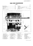
 Next
Next
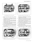
FOUR SPEEED TRANSMISSION 7 I2 GENERAL DESCRIPTION A great deal of similarity and interchangeability now except the selector shaft and selector finger are located exists between the new 3 and 4 speed transmissions on the cover The backup lamp switch is located on the Only these 4 speed differences as they affect service cover position described under Corvair three speed will be covered here Other 4 speed service procedures transmission cover assembly are similar to the Corvair 3 speed transmission and The following parts are the same as those used in the are not repeated in this section Corvair three speed transmission cover head to shaft pins interlock and detent balls detent springs third and MAINSHAFT ASSEMBLY fourth shifter shaft the three speed Seedhd and third Assembly procedures described under Corvair Three Shifterblshafg att third agd fomit Sh ftt heal imd img Speed Transmission also apply to this transmission f1 1rkya S b1 Sp 6 seem an wd S if gr ea However the synchronizer assembly at the front of the Disasseglbly ami Aqsembly Procedures are cgvergd mainshaft is used for the third and fourth rather than the second and third shift The synchronizer assembly at the m thm Sectmm rear of the mainshaft is used for the first and second rather than the first and reverse shift Gear teeth cut in CASE the first and second synchronizer sleeve distinguish it The case has 3 filler plug Opening On the righbhand from the third and fourth synchronizer sleeve All parts Side It pmvidgs for Six bolt attachment to the carrier except uw gears and the Mgt and Seccmd Synchmmzer Holes are added to the Corvair three speed transmission sleeve in the new four speed transmission mainshaft Case to accommodate the familiar r v rse inhibimr assembly are MSO used in the Cmavair three Speed parts used in the four s eed transmissions only If nec transmission mainshaft assembly However starting essar these parts may ig removed by punching Out the from the front gears on the mainshaft are third second tWO gage Welsh plugs See View On Fig 1 CTOSS and first rather than second first and reverse A fourth section blocker ring is used between the l 2 synchronizer as sembly and first gear on the four speed transmission REVERSE IDLER GEAR PARTS M SCELL NE US This transmission includes the Corvair three speed b Thu 13 A TGYGITSB idler gear and Shaft rammed transmission clutch gear bearing retainer gasket se Y a Wciodmff key Ehmmatmn Of the thrust washer be lector shaft and selector shaft seal A new selector tween the gear and C3 S and removal Of the Snap ring finger has been designed to both engage the shifter head gmcwe to allow movement Of the reverse idler g ar selector slots in the cover as well as the reverse in distinguishes this shaft from the three speed transmis hibitor located in the base 0 the Case sion reverse idler shaft Otherwise service procedure is the same as for the three speed transmission TOOLS COVER ASSEMBLY The same dummy countershaft Tool J 22246 used with The cover on the new four speed transmission is lo the three speed transmissions can also be used with the cated on the left hand side of the case All shift controls four speed transmission MAINTENANCE AND ADJUSTMENTS SIDE CQVER A EMB Y Fjg 23 3 Insert interlock pin in the hole of the interlock detent Disassembly in the longest of the shafts with three detents the third and fourth shaft Insert the shaft three detents i i h i OS i t O i Oii Piiis r iiiniiig ihe Shifter msi ihid the middle hole of the ieri hahd hdss di the cover othtte rt i 2 With upper and lower shifter shafts in neutral detent Of the ihirdaang fgugtgughqifgsrgggg g Y r S gl X positions remove the center shifter shaft and head bh The third and fourth Shifter head and fork aS OY Sliding the Shaft through the cover bOSS S sembly has a larger fork than the first and second 3 Remove thO O O WO Ohiiwi Shafts OOO OOOOO shifter head and idik assembly ii CED be identified 4 Remove the 3 poppet strings and 7 detentballs fwm by the Shgft hole between the notch and the selector the cover bosses Remove the interlock pm from the Slot 34 Shim Shift 4 Assemble the third add fourth shifter head and rdrk A mb y assembly over the shaft with the fork hole to the l Turn inside of cover up so that single attaching hole 1 ighY h3 d side and thc S l C 0F slot d0WHW 1 d Om flange 15 at the t0p 5 Complete insertion of shaft through the right hand 2 Drop a poppet spring and ball in each of the two boss while lining up the shaft detents with the detent holes in the right hand boss of the cover All detent ball Stop at the 2nd neutral speed detent springs are identical all detent and interlock balls 6 Line up holes in head and shaft insert roll pin All are identical head attaching pins are the same Fig 3B CORVAIR SHOP MANUAL SUPPLEMENT