Jeep Parts Wiki | Ford Parts Wiki
Home | Search | Browse | Marketplace | Messages | FAQ | Guest
|
Corvair Chassis Shop Manual Supplement December 1965 |
|
Prev
 Next
Next
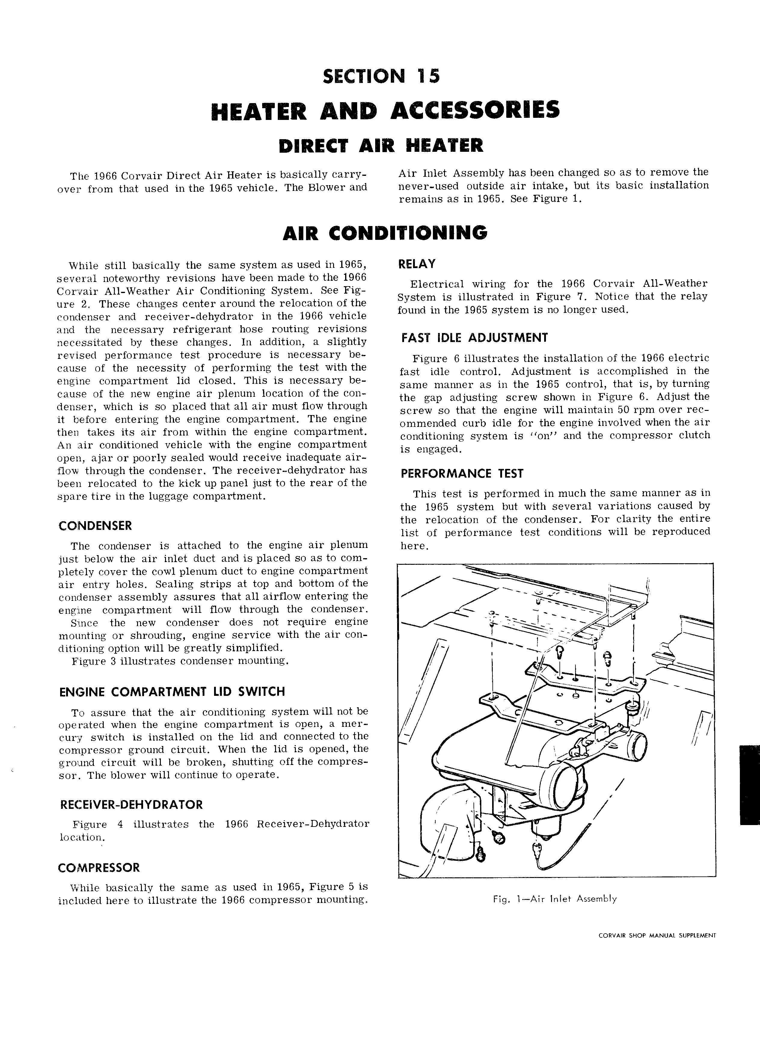
SECTION 15 DIRECT AIR HEATER The 1966 Corvair Direct Air Heater is basically carry Air Inlet Assembly has been changed so as to remove the over from that used in the 1965 vehicle The Blower and never used outside air intake but its basic installation remains as in 1965 See Figure 1 AIR CONDITIONING While still basically the same system as used in 1965 RELAY several noteworthy revisions have been made to the 1966 Corvair All Weather Air Conditioning System See Fig Elecullc l wlrmg fer me 1966 COYYRUA Albweather ure 2 These changes center around the relocation of the Systew ls luustmted m F1gur 7 NOUCG that the relay eenneneee nne n eeenee eenyneeeee in the ieee venneie fwd mihe 1965 System is mee um and the necessary refrigerant hose routing revisions necessitated by these changes ln addition a slightly FAST IDI E ADJUSTMENT revised p9rfOrmLmC test pmcedur IS necessary be Figure 6 illustrates the installation of the 1966 electric Cau w Of the necesslty Of p rfOrm1 g th test Wlth the fast idle control Adjustment is accomplished in the engine compartment lid closed This is necessary be Same manner as in the 1965 wntml that is by turning cause of the new engine air plenum location ofthe con the gap adjusting Screw Shown in Flgum 6 Adjust the Cieme which Se pleeedimi all er must HOW ihre eh screw ee that ne engine win maintain en rpm evee eee ii before entering the engine compartment The engine Ommended Cuyb me fen the engine involved when the air then takes its air from within the engine compartment Condimmmg System is 011 and the COmpr SSOI clutch An air conditioned vehicle with the engine compartment is Engaged open ajar or poorly sealed would receive inadequate air flow through the condenser The receiver dehydrator has PERFORMANCE TEST been relocated to the kick up panel just to the rear of the spare tire in the luggage compartment This test is performed in much the same manner as in the 1965 system but with several variations caused by COTNDENSER the relocation of the condenser For clarity the entire list of performance test conditions will be reproduced The condenser is attached to the engine air plenum here just below the air inlet duct and is placed so as to com pletely cover the cowl plenum duct to engine compartment air entry holes Sealing strips at top and bottom of the TI condenser assembly assures that all airflow entering the Ely l engine compartment will flow through the condenser Q Since the new condenser does not require engine mounting or shrouding engine service with the air con VJ I J ditioning option will be greatly simplified Figure 3 illustrates condenser mounting A I lb j I I ui l at ENGINE COMPARTMENT LID SWITCH L To assure that the air conditioning system will not be C S I operated when the engine compartment is open a mer 9 J fl cury switch is installed on the lid and connected to the V fs compressor ground circuit When the iid is gpened the ee ground circuit will be broken shutting off the compres R e t sor The blower will continue to operate 3 e M x RECEIVER DEHYDRAT A I Figure 4 illustrates the 1966 Receiver Dehydrator T et W location A X7 Y Q COMPRESSOR j While basically the same as used in 1965 Figure 5 is included here to illustrate the 1966 compressor mounting Fig I Air Inlet Assembly CORVAIR SHOP MANUAL SUPPLEMENT