Jeep Parts Wiki | Ford Parts Wiki
Home | Search | Browse | Marketplace | Messages | FAQ | Guest
|
Corvair Chassis Shop Manual Supplement December 1966 |
|
Prev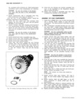
 Next
Next
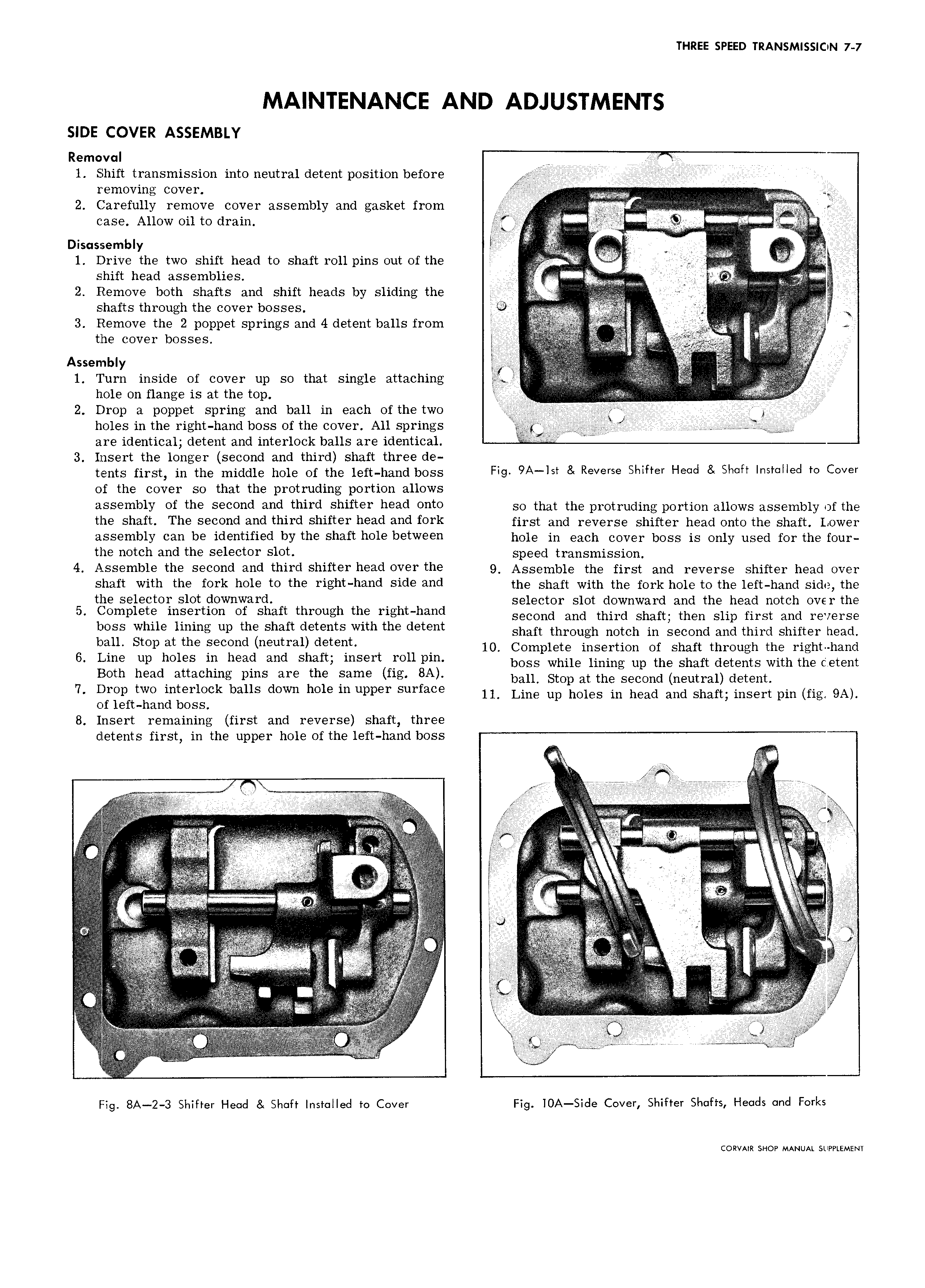
THREE SPEED TRANSMISSION 7 7 SIDE COVER ASSEMBLY Removal N 1 Shift transmission into neutral detent position before S removing cover g 2 Carefully remove cover assembly and gasket from I v case Allow oil to drain S fry S S S S Disassembly lr RAI it v Vrv v 1 Drive the two shift head to shaft roll pins out of the 2 V I yl S it shift head assemblies ss V w 7 V t 2 Remove both shafts and shift heads by sliding the f Q V lR s shafts through the cover bosses f s jj X 3 Remove the 2 poppet springs and 4 detent balls from f S W f j the COVE b0SS S E S l sth Assembly 1 Turn inside of cover up so that single attaching rjvv h ole on flange is at the top I I 2 Drop a poppet spring and ball in each ofthe two i y S holes in the right hand boss of the cover All springs p jg g A lgg 2S I 4 are identical detent and interlock balls are identical t S 3 Insert the longer second and third shaft three de tr mts first in the middle hglg Of hg 1gff hg dbOSS Fig 9A lst Reverse Shifter Head 8 Shaft Installed to Cover of the cover so that the protruding portion allows k1SS mblY of the second and thiI l Sl1ifl I hO3d onto so that the protruding portion allows assembly ofthe ll1 Shaft This S C0 d and lhifd Shift 1 h ad 3 l fork first and reverse shifter head onto the shaft Lower assembly can be identified by the shaft hole between hole in sash Csvsr boss is Only used for lhs Our the notch and the selector slot Speed transmission 4 Assemble the second and third shifter head over the g Assgmblg lhs first and rsvsrss Shifter hsad Ovsr Shaft with the fork hole to the risht hahd side and the shaft with the fork hoie to the iert hand side the the S9l Cl0I slot d0WHW l1 d selector slot downward and the head notch over the 5 m 1 t m Of Shaft thmugh the Msht hm second and mira shaft then slip at Si and we SQ boss whlle lmms up the Shaft detents Wllh the detent shaft through notch in second and third shifter head mu Smp at the S C d neutral d t l 10 Co iete S se to or sn rr th ou h the right ham 6 I me up holes in hse wd Shafts mee 011 pm bO T pWh 1iimi Ep the siaft dgtefts with the Cam Both head attaching pms are the same fig 8A ban Stop at the Secmd n utm1 d t nt 7 Drop two interlock balls down hole in upper surface IL Lim up holes in head and Shaft insert pm fig 9A of left hand boss 8 Insert remaining first and reverse shaft three detents first in the upper hole of the left hand boss ii t t M D 4 ll l if r leli fflit X F if if l i l II t tlt lg t st il ll ei S i t i S S V et l I O S s SS 3 S or s h SoSii r S S S r sr V l s i S S V F H l ll ti Al fkkkr t l l l t t Sttt l i l S i S f SS 2 i S S S t S if n SS Saw SSS S i S Stt t V ggriii I S 2 S O Si t S S S S l SS t S S S S S S S S S S t t t t tg SS S S T Sl r I OO st S l S Ss S Of S Sl t ilii h h E is Fig 8A Z 3 Shifter Head Shaft Installed to Cover Fig IOA Side Cover Shifter Shafts Heads and Forks CORVAIR SHOP MANUAL SUPPLEMENT