Jeep Parts Wiki | Ford Parts Wiki
Home | Search | Browse | Marketplace | Messages | FAQ | Guest
|
Corvair Chassis Shop Manual Supplement December 1966 |
|
Prev

 Next
Next
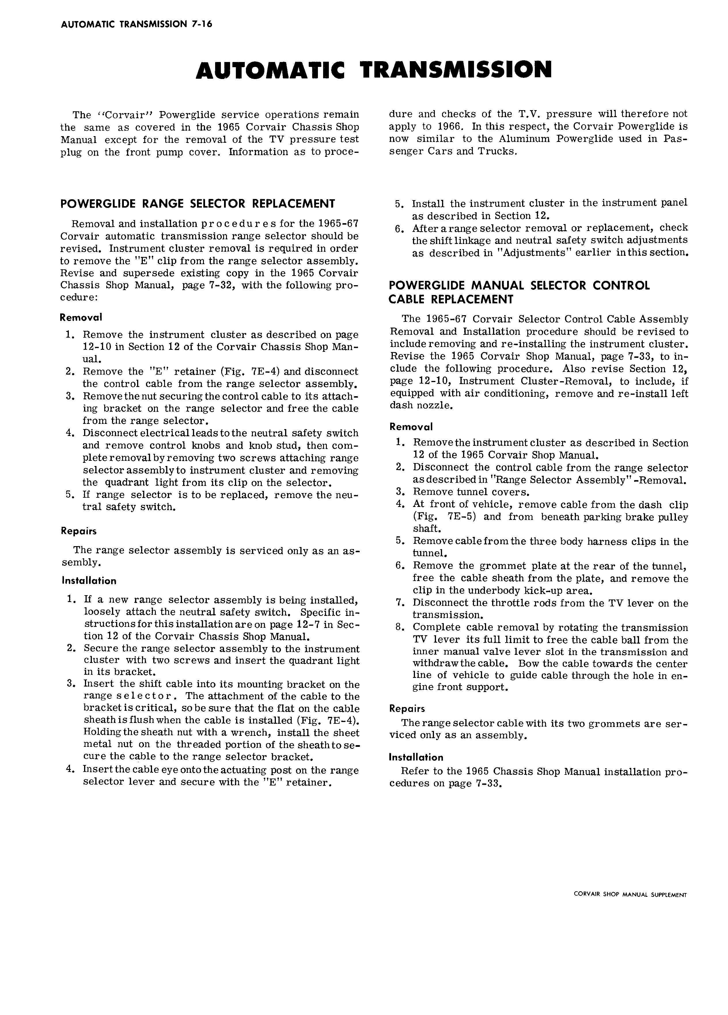
AUTOMATIC TRANSMISSION 7 16 The Corvair Powerglide service operations remain dure and checks of the T V pressure will therefore not the same as covered in the 1965 Corvair Chassis Shop apply to 1966 In this respect the Corvair Powerglide is Manual except for the removal of the TV pressure test now similar to the Aluminum Powerglide used in Pas plug on the front pump cover Information as to proce senger Cars and Trucks POWERGLIDE RANGE SELECTOR REPLACEMENT 5 Install the instrument cluster in the instrument panel as described in Section 12 Removal and 1oSt3 uet1On pr O C edu r Q S for the 1965 67 6 After arange selector removal or replacement check Corvair automatic transmission range selector should be the Shift imkage and neutrai safety svvitcn ediustments revised Instrument cluster removal is required in order as described in nndjustmentsn earlier inthis Seetiorn to remove the E clip from the range selector assembly Revise and supersede existing copy in the 1965 Corvair Chassis Shop Manual page 7 32 with the following pro POWERGLIDE MANUAL SELECTOR CONTROL Cedurei CABLE REPLACEMENT Removul The 1965 67 Corvair Selector Control Cable Assembly 1 Remove the instrument c1uster as described on page Removal and Installation procedure should be revised to 12 10 in Section 12 ot the Corvair Chassis snob Men include removing and re installing the instrument cluster ue 1 Revise the 1965 Corvair Shop Manual page 7 33 to in 2 Remove the E retainer Fig 7E 4 and disconnect clude the following procedure Also revise Section 12 the control cable from the range selector assembly page 1240 instrument CloeteI Removo 1 to inolude if 3 Remove the nut securing the control cable to its attach eqolppeo vvlth an ooooltiooiogr remove o oo reooeteu left ing bracket on the range selector and free the cable oooh oozz1e from the range selector Removal 4 Disconnect electrical leads to the neutral safety switch end remove contro1 knobs end knob stud then com 1 Removethe instrument cluster as described in Section plete removal by removing two screws attaching range lz of the 1965 Corvair Shop Manuel se1ectoressemb1vto instrument ciuster end removing 2 Disconnect thencontrol cable from the range selector the quedrent 1ient from its ciin on the se1ector as described in Range Selector Assembly Removal 5 If range selector is to be replaced remove the neu 3 Remove tunnel Covers tre 1 setetv svvitcn 4 At front of vehicle remove cable from the dash clip Fig 7E 5 and from beneath parking brake pulley Repairs shaft 5 Remove cable from the three body harness clips in the The range selector assembly is serviced only as an as tunnel sembly 6 Remove the grommet plate at the rear of the tunnel instcuutiou free the cable sheath from the plate and remove the clip in the underbody kick up area 1 lf a new range selector assembly is being installed 2 Disconnect the throttle rods from ins TV lever on ins loosely attach the neutral safety switch Specific in t1 anSmjSSiOn struotionsforthisinstallation are on page 12 7 in seo 8 Complete oooio removal by rotating mo transmission tion 12 of the Corvair Chassis Shop Manual TV lever its full limit to free the cable ball from the 2 Secure the range ss1 0t0I assembly to the instrument inner manual valve lever slot in the transmission and Cluster with two screws and insert the quadrant light witndrnwtno oobio Bow the cable towards tho center in its bracket line of vehicle to guide cable through the hole in en 3 Insert the shift cable into its mounting bracket on the gine front Support range s el e c t o r The attachment of the cable to the bracket is critical so be sure that the flat on the cable Repairs sheath is flush when ths Csbls is mst Usd Fi 7E 4 The range selector cable with its two grommets are ser Holding the sheath nut with a wrench install the sheet vicgd Only as an assembly metal nut on the threaded portion of the sheath to se cure the cable to the range selector bracket lnsI ll Iion 4 Insert the cable eye onto the actuating post on the range Refer to the 1965 Chassis Shop Manual installation pro selector lever and secure with the E retainer cedures on page 7 33 CORVAIR SHOP MANUAL SUPPLEMENT

 Next
Next