Jeep Parts Wiki | Ford Parts Wiki
Home | Search | Browse | Marketplace | Messages | FAQ | Guest
|
Corvair Chassis Shop Manual Supplement December 1966 |
|
Prev

 Next
Next
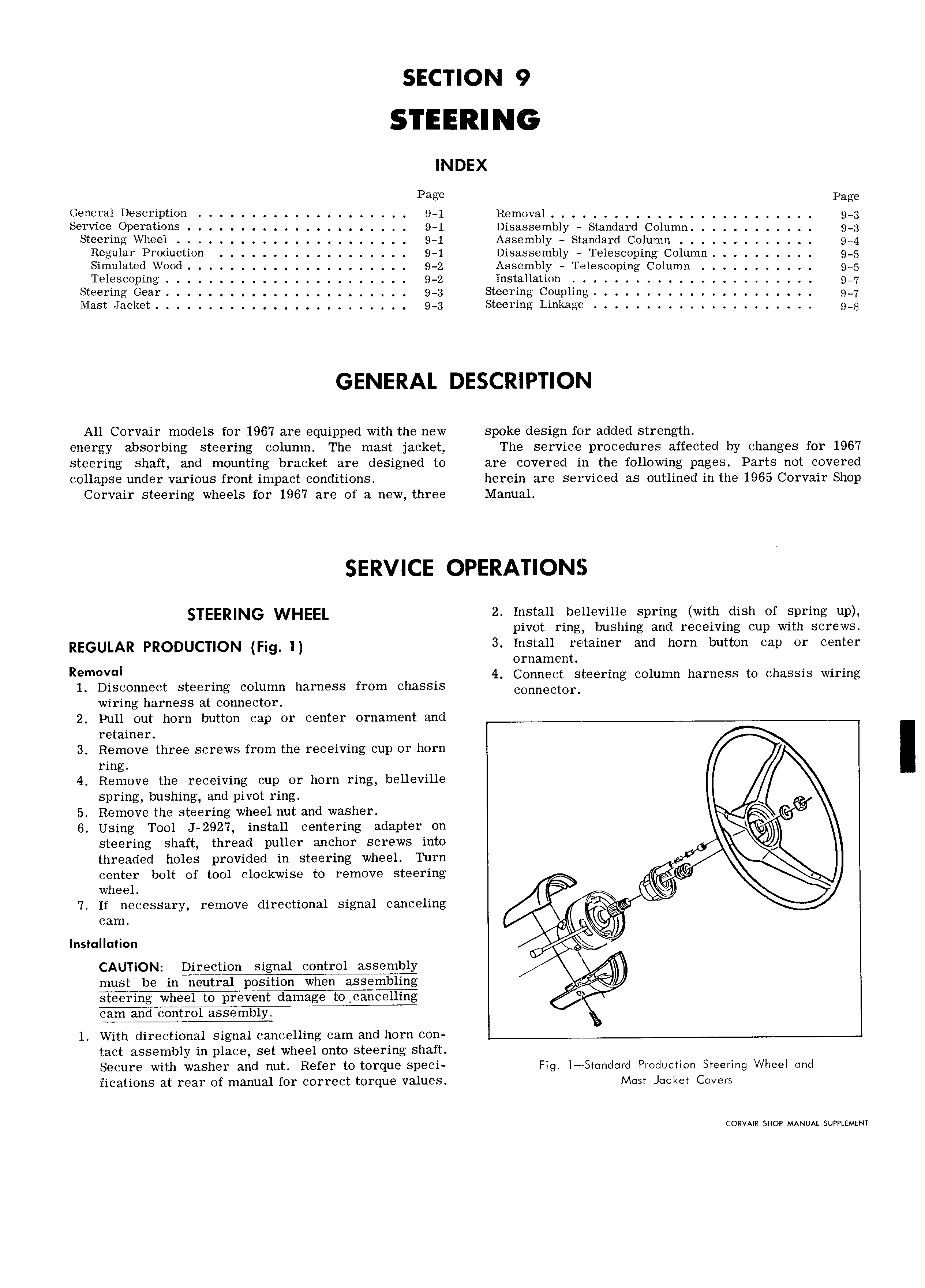
SECTION 9 INDEX Page Page General Description 9 1 Removal 9 3 Service Operations 9 1 Disassembly Standard Column 9 3 Steering Wheel 9 1 Assembly Standard Column 9 4 Regular Production 9 1 Disassembly Telescoping Column 9 5 Simulated Wood 9 2 Assembly Telescoping Column 9 5 Telescoping 9 2 lnstallation 9 7 Steering Gear 9 3 Steering Coupling 9 7 Mast Jacket 9 3 Steering Linkage rpg GENERAL DESCRIPTION All Corvair models for 1967 are equipped with the new spoke design for added strength energy absorbing steering column The mast jacket The service procedures affected by changes for 1967 steering shaft and mounting bracket are designed to are covered in the following pages Parts not covered collapse under various front impact conditions herein are serviced as outlined in the 1965 Corvair Shop Corvair steering wheels for 1967 are of a new three Manual SERVICE OPERATIONS EER NG WHEEL 2 Install belleville spring with dish of spring up pivot ring bushing and receiving cup with screws REGULAR PRODUCUQN Fjg 3 Install retainer and horn button cap or center ornament R I 4 Connect steering column harness to chassis wiring 1 Disconnect steering column harness from chassis cOIm8CtOr wiring harness at connector 2 Pull out horn button cap or center ornament and retainer 3 Remove three screws from the receiving cup or horn ring 4 Remove the receiving cup or horn ring belleville spring bushing and pivot ring 5 Remove the steering wheel nut and washer 6 Using Tool J 2927 install centering adapter on steering shaft thread puller anchor screws into threaded holes provided in steering wheel Turn center bolt of tool clockwise to remove steering wheel 7 If necessary remove directional signal canceling Installation CAUTION Direction signal control assembly must be invneutral position when assembling 4 steering wheel to prevent damage to cancelling control 1 With directional signal cancelling cam and horn con 1 act assembly in place set wheel onto steering shaft Secure with washer and nut Refer to torque speci Fig l Srondord Production Steering Wheel ond fications at rear of manual for correct torque values Meer Jacket Covers CORVAIR SHOP MANUAL SUPPLEMENT

 Next
Next