Jeep Parts Wiki | Ford Parts Wiki
Home | Search | Browse | Marketplace | Messages | FAQ | Guest
|
Corvair Chassis Shop Manual Supplement December 1966 |
|
Prev

 Next
Next
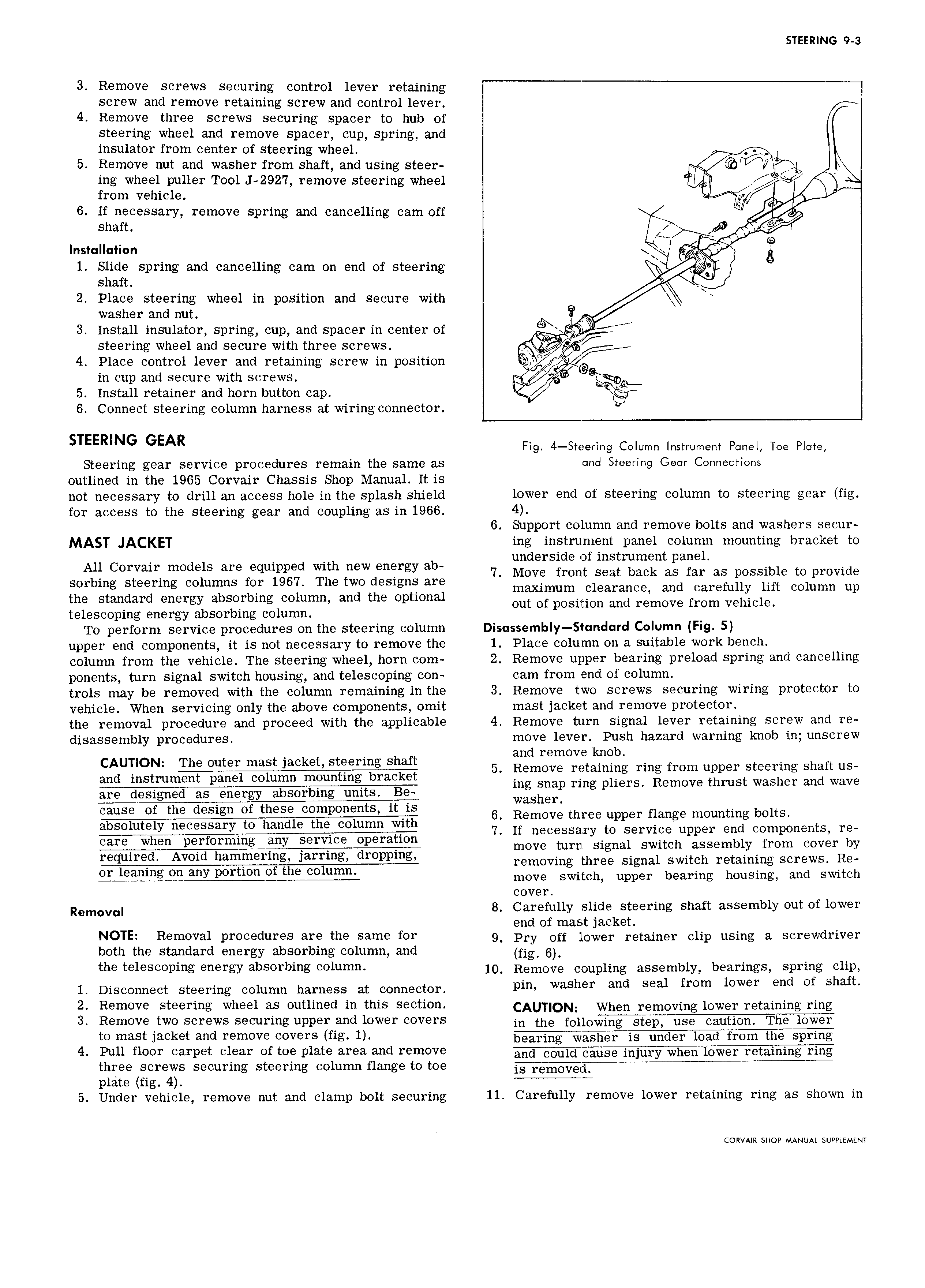
STEERING 9 3 3 Remove screws securing control lever retaining screw and remove retaining screw and control lever 4 Remove three screws securing spacer to hub of steering wheel and remove spacer cup spring and insulator from center of steering wheel 5 Remove nut and washer from shaft and using steer 77oV ing wheel puller Tool J 2927 remove steering wheel 1 from vehicle Y 6 If necessary remove spring and cancelling cam off E shan p Installation l r 1 Slide spring and cancelling cam on end of steering shaft M 2 Place steering wheel in position and secure with washer and nut o 3 Install insulator spring cup and spacer in center of steering wheel and secure with three screws 4 Place control lever and retaining screw in position V in cup and secure with screws oe qD 5 Install retainer and horn button cap 6 Connect steering column harness at wiring connector Fig 4 Steering Column Instrument Panel Toe Plate Steering gear service procedures remain the same as rind Steering Gear Connections outlined in the 1965 Corvair Chassis Shop Manual It is not necessary to drill an access hole in the splash shield lower end of steering column to steering gear fig for access to the steering gear and coupling as in 1966 4 6 Support column and remove bolts and washers secur MAST JACKET ing instrument panel column mounting bracket to underside of instrument panel All Cowan models are eqmpp d wlth new energy ab 7 Move front seat back as far as possible to provide sorbing steering columns for 1967 The two designs are maximum clearance and Carefully lift Column up the standard energy absorbing column and the optional out Of position and I mOV from Vehicle telescoping energy absorbing column To perform service procedures on the steering column Disassembly Standard Column Fig 5 upper end components it is not necessary to remove the 1 Place column on a suitable work bench column from the vehicle The steering wheel horn com 2 Remove upper bearing preload spring and cancelling ponents turn signal switch housing and telescoping con cam from end of column trols may be removed with the column remaining in the 3 Remove two screws securing wiring protector to vehicle When servicing only the above components omit mast jacket and remove protector the removal procedure and proceed with the applicable 4 Remove turn signal lever retaining screw and re disassembly procedures move lever Push hazard warning knob in unscrew and remove knob AUl 5 Remove retaining ring from upper steering shaft us ing snap ring pliers Remove thrust washer and wave are designed as energy absorbing units Be Washer 6 Remove three upper flange mounting bolts 7 If necessary to service upper end components re move turn signal switch assembly from cover by qu1r d Avmd hamlnermg 3 rrmg drOppmg removing three signal switch retaining screws Re move switch upper bearing housing and switch cover R mC v 8 Careigully slideksteering shaft assembly out of lower end o mast jac et NOTE R m v 1 Proeednres are me Same for 9 Pry off lower retainer clip using a screwdriver both the standard energy absorbing column and fig 6 t 1 S pi g energy absorbing Column 10 Remove coupling assembly bearings spring clip 1 Disconnect steering column harness at connector mm Washer and Seal from lowor ond of shaft 2 Remove steering wheel as outlined in this section CAUTION when removing lgwgr retaining ring 3 Remove two screws securing upper and lower covers in the fOuO to mast jacket and remove covers fig 1 4 Pull floor carpet clear of toe plate area and remove three screws securing steering column flange to toe plate fig 4 5 Under vehicle remove nut and clamp bolt securing 11 Carefully remove lower retaining ring as shown in CORVAIR SHOP MANUAL SUPPLEMENT

 Next
Next