Jeep Parts Wiki | Ford Parts Wiki
Home | Search | Browse | Marketplace | Messages | FAQ | Guest
|
Corvair Chassis Shop Manual Supplement December 1966 |
|
Prev

 Next
Next
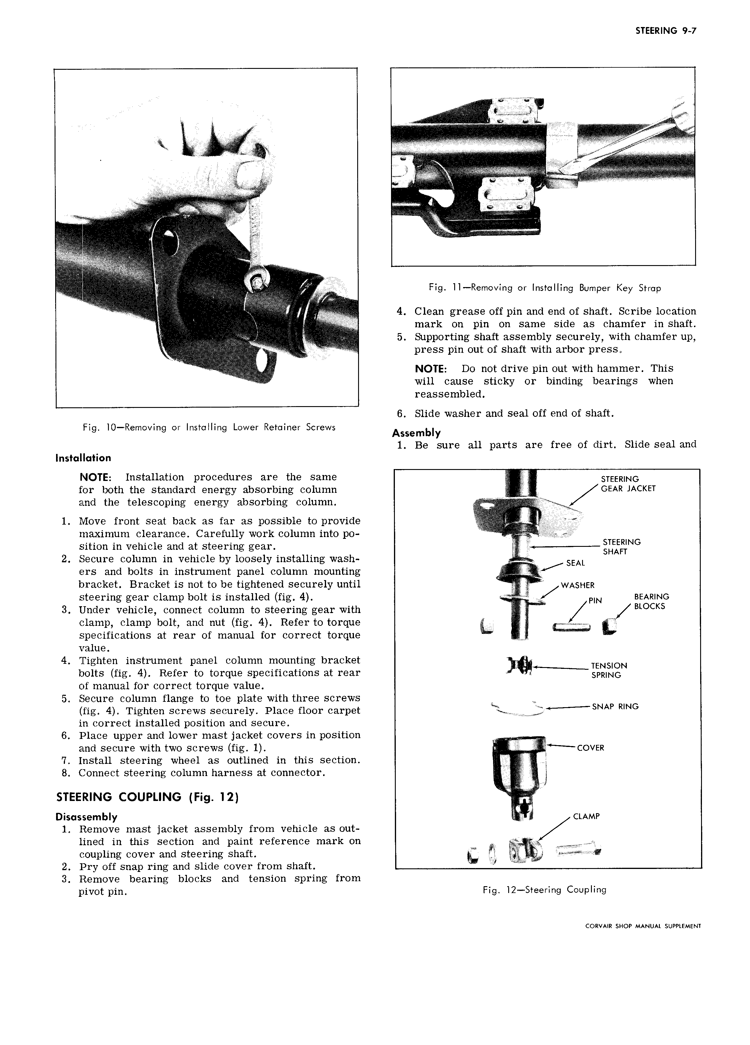
STEERING 9 7 I ly EE EE sit it E iii E i i E u EE ii E i i A M V y E E y y S VV E EE I I F l E EEZ V W I rr k r EEEERE E I EE EE T r V r EEE on E E E w l V E V E4 v E I l ie s E S H y y y VVV Ig emovmg or Installing Bumper Key Strap E g LL V VV V V hh if 4 Clean grease off pin and end of shaft Scribe location N I V V i i mark on pin on same side as chamfer in shaft I M 5 Supporting shaft assembly securely with chamfer up I I E e E E rE press pin out of shaft with arbor press NOTE Do not drive pin out with hammer This I will cause sticky or binding bearings when reassembled 6 Slide washer and seal off end of shaft Fig IO Removing or Installing Lower Retainer Screws Assembly 1 Be sure all parts are free of dirt Slide seal and Installation NOTE Installation procedures are the same STEERING for both the standard energy absorbing column I GEAR JACKET and the telescoping energy absorbing column V E 1 Move front seat back as far as possible to provide maximum clearance Carefully work column into po l I ia sition in vehicle and at steering gear QLEESNG 2 Secure column in vehicle by loosely installing wash SEAL ers and bolts in instrument panel column mounting bracket Bracket is not to be tightened securely until E WASHER steering gear clamp bolt is installed fig 4 A i PIN BEARING 3 Under vehicle connect column to steering gear with I 4 BLOCKS clamp clamp bolt and nut fig 4 Refer to torque L mis specifications at rear of manual for correct torque yy y I value 4 Tighten instrument panel column mounting bracket TENSION bolts fig 4 Refer to torque specifications at rear SPRING of manual for correct torque value 5 Secure column flange to toe plate with three screws W fig 4 Tighten screws securely Place floor carpet i y f SNAP RING in correct installed position and secure 6 Place upper and lower mast jacket covers in position Ny and secure with two screws fig 1 COVER 7 Install steering wheel as outlined in this section i 8 Connect steering column harness at connector I STEERING COUPLING Fig I2 gg Disassembly CLAMP 1 Remove mast jacket assembly from vehicle as out lined in this section and paint reference mark on y y A y coupling cover and steering shaft gy 2 Pry off snap ring and slide cover from shaft E 3 Remove bearing blocks and tension spring from pivot pin Fig i2 Steering Coupling CORVAIR SHOP MANUAL SUPPLEMENT

 Next
Next