Jeep Parts Wiki | Ford Parts Wiki
Home | Search | Browse | Marketplace | Messages | FAQ | Guest
|
Corvair Chassis Shop Manual Supplement December 1966 |
|
Prev

 Next
Next
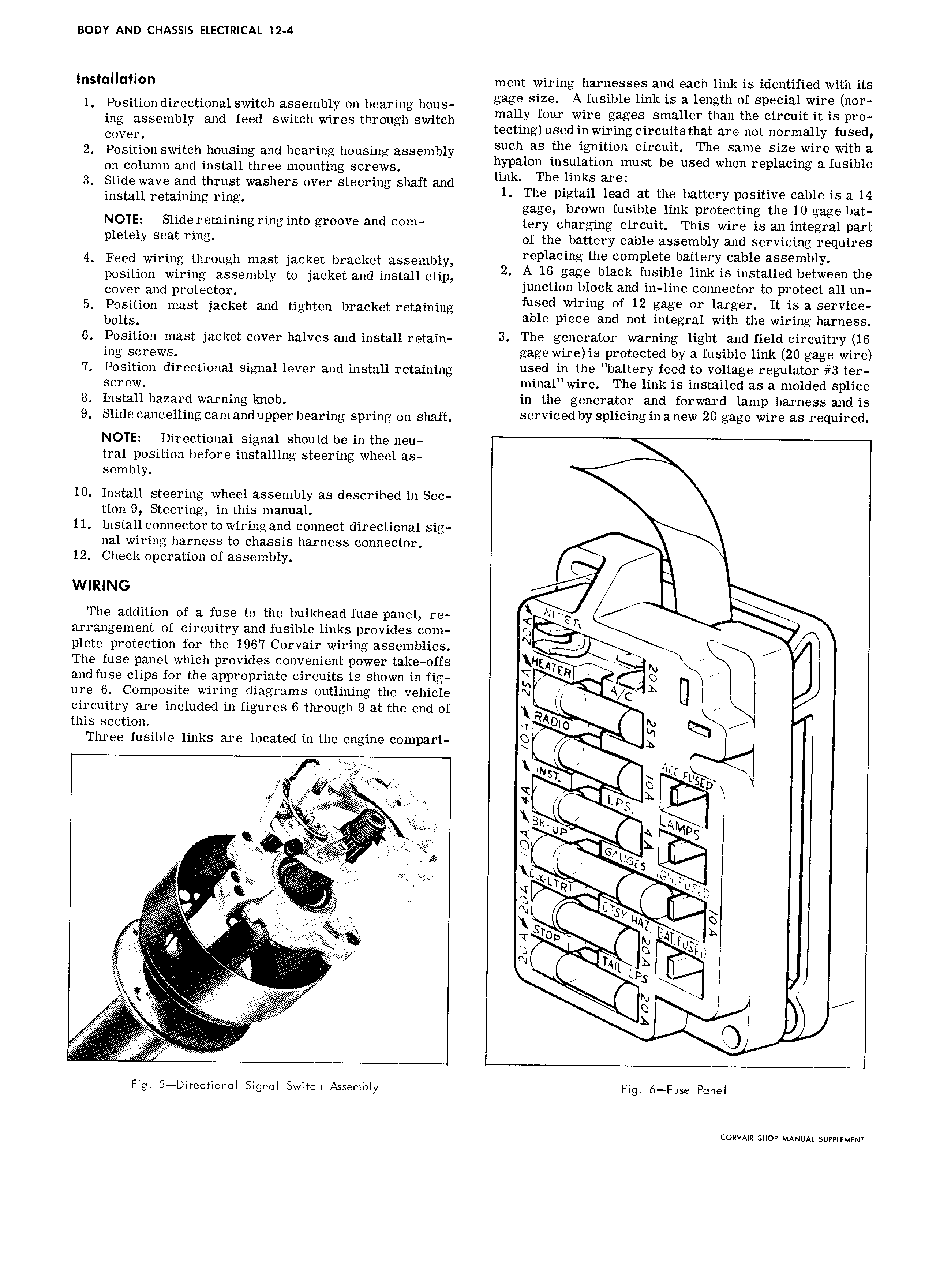
BODY AND CHASSIS ELECTRICAL I2 4 lnsfulluflon ment wiring harnesses and each link is identified with its 1 Position directional switch assembly on bearing hous gage SIZE A fuS1b1 lmk 1S a length Of Special wu mr mally four wire gages smaller than the circuit it is pro ing assembly and feed switch wires through switch Cover tecting used in wiring circuits that are not normally fused 2 Position switch housing and bearing housing assembly iuchl as Fha llgsltwn clfcguh TSB same Slug Wuagfwllgla on column and install three mounting screws 1553 Oghmill mn Wus Q use W en rep acmg a HSI G 3 Slide wave and thrust washers over steering shaft and 6 m S M6 install retaining ring 1 The pigtail lead at the battery positive cable is a 14 gage brown fusible link protecting the 10 gage bat NOTE Slld 1 t3 llllllg Flllg lllt0 gl 00V mid 0lll tery charging circuit This wire is an integral part Plelely seat Pills of the battery cable assembly and servicing requires 4 Feed wiring through oooh jacket hhoohot assembly 2 gsglgsme th ssljsgetslheitsii sssls ssssmhlr position wiring assembly to jacket and install clip gag ac S1l m 1S mstaued between lhs cover and protector junction block and in line connector to protect all un 5 Position mast jacket and tighten bracket retaining fused Yvlmng sf 12 gage sr lajrgeh It a Servlce bolts able piece and not integral with the w1r1ng harness 6 Position moot jacket oovoh halves and install retain 3 The generator werhihg light end field circuitry 16 Ing sCy WS gage wire is protected by a fusible link 20 gage wire 7 Position directional signal lever and install retaining used in the hettery feed te veltese resuleter 3 ter ScI w minal wire The link is installed as a molded splice 3 hqgtall hazard Warning Im0b in the generator and forward lamp harness and is 9 Slide C3 HCB1l1llg oooh and upper ooohhhg spring oh shaft serviced by eplieihgihehew 20 sage wire ee required NOTE Directional signal should be in the neu tral position before installing steering wheel as sembly 10 lnstall steering wheel assembly as described in Sec tion 9 Steering in this manual 11 Install connector to wiring and connect directional sig nal wiring harness to chassis harness connector 12 Check operation of assembly l WIRING 4 I The addition of a fuse to the bulkhead fuse panel re Nlf I arrangement of circuitry and fusible links provides com U plete protection for the 1967 Corvair wiring assemblies N The fuse panel which provides convenient power take offs H ATE N and fuse clips for the appropriate circuits is shown in fig fj R 0 ure 6 Composite wiring diagrams outlining the vehicle N A Q L U I circuitry are included in figures 6 through 9 at the end of this section rr AMO X Three fusible links are located in the engine compart Q Q y I WST M F SzD I lm vlwww h g I is h li 9 o l G y V I i M F t K LT cs low i el I M hi S i It N CT I H ii G to lh r We zh l hk if Op v fg Altlugh gi V My I hir L x L I lh ii j d r M V I Q l 1 t ii I t Fig 5 Dlrectl0n l Slgnol Switch Assembly Fig 6 Fuse Panel CORVAIR SHOP MANUAL SUPPLEMENT

 Next
Next