Jeep Parts Wiki | Ford Parts Wiki
Home | Search | Browse
|
Corvair Chassis Shop Manual Supplement December 1967 |
|
Prev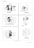

 Next
Next
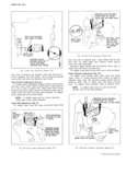
ENGINE FUEL 6M 3 TSG hjmdel Htsagzgior fig 124 usjd asba Setcondalyy The Model HV Carburetor fig 2 is basically the same C 3 r ur OE On 6 p Engm X Car ure QrS ls as outlined in the 1965 Corvair Shop Manual with calibra basically the same as outlined in the 1965 Corvair Shop tion Changes and the addition Of 3 www idle air bleed Manual except for calibration changes and the addition fig 3 The power mcrichmgnt S Stem has been r of linkage interim 1965 to lockout the carburetor until mmjed fmm Model HV Carburetogls On Air Injection the engine has warmed up Reactor S ystem equipped eng1nes fig 3 tk In aidltjion A flxgd fljel feedd Sglstem h S bien aggfd All adjustment procedures for both carburetors are le SP On my Car um Ors an 8 MPP era Or p P 1 new due to calibration changes and will be made with the used only as a throttle return plunger and no pump cup Universal Carburetor Gauge Set 9 789 is used FIo t Level Adjustment Fig 4 With the air horn inverted and the gasket in place check height of each float Bend tang which contacts needle until each pontoon is set to specified dimension 7 Float pontoons should be parallel with air horn surface when set correctly Align floats to avoid interference m bewi j F o t Drop Ad ustment Fi 5 I I 9 With the air horn assembly held upright and floats ix 1 Suspended fygglyy 3 Sl1I dimension fI OH HIT hOI H wi 7 s gasket to bottom of float pontoon at toe adjust to speci JF fied dimension by bending tang which contacts seat at rear of float arm GAUGE FROM BEND TANG AIR HORN GASKET Pump RMI AdI F 9 6I to ADJUST to sorrom or nom Back out idle stop screw until the throttle valves are AT TOE completely closed in bore Bend pump rod as shown j until the index line on upper pump lever aligns with sharp edge on air horn casting Idle Vent Vulve Adjustment Fig 7 To adjust bend the tang on the throttle lever so that when the vent valve just starts to open the proper gauge Fig 5 F O t Drop Adjustment Model H HV ALIGN INDEX i MARK ON LEVER WITH GAUGE FROM tor si SHARP EDGE OF FLOAT TO AIR k ON A T NG HORN GASKET 5 BEND TANG L TO ADJUST U A itq j THROTTLE VALVES FULLY f Q CLOSED I 5 QD 4 BEND TO im ADJUST Fig 4 Fl0 t Level Adjustment Model H HV Fig 6 Pump Rod Adjustment Model H St HV CORVAIR SHOP MANUAL SUPPLEMENT