Jeep Parts Wiki | Ford Parts Wiki
Home | Search | Browse
|
Corvair Chassis Shop Manual Supplement December 1967 |
|
Prev
 Next
Next
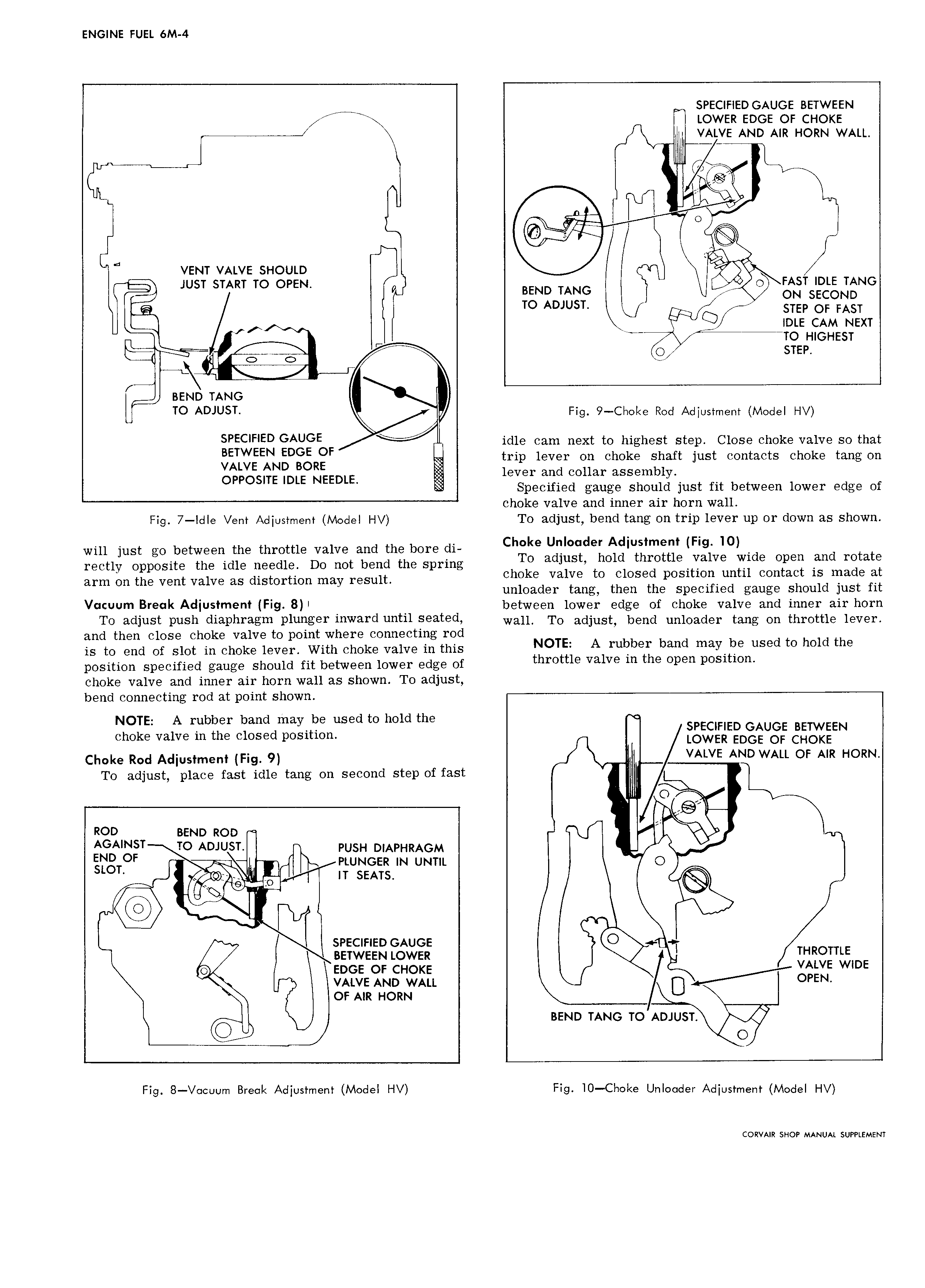
ENGINE FUEL 6M 4 E SPECIFIED GAUGE BETWEEN LOWER EDGE or CHOKE VALVE AND AIR HORN WALL G A UG O 3 VENT VALVE SHOULD L JUST START TO OPEN I BEND TANG 0 FAST IDLE TANG T ON SECOND TD ADJUST Q STEP ot FAST gf 4 IDLE CAM NEXT E EH TT0 HIGHEST I att BEND TANG TO ADJUST Fig 9 Choke Rod Adjustment Model HV SPECIFIED GAUGE idle cam next to highest step Close choke valve so that itJ F tNEDggR t trip lever on choke shaft just contacts choke tang on OPPOSITE IDLE NEEDLE lever and collar assembly Specified gauge should just fit between lower edge of choke valve and inner air horn wall Fig 7 IdIe Vent Adjustment Model HV To adjust bend tang on trip lever up or down as shown will just go between the throttle valve and the bore di C d jj s jd Iz jgI j 1j i I iV INid Open and rotate tl t th dl dl D tb dthes n gi gntjggoj ni Valielag dtjggorgon 32 Or SiIjt pm g choke valve to closed position until contact is made at unloader tang then the specified gauge should just fit V Um B I AdiU5tm Fig 8 between lower edge of choke valve and inner air horn T0 adjust Push diaphragm Plunge Inward 1S f d wall To adjust bend unloader tang on throttle lever and then close choke valve to point where connecting rod is to end of slot in choke lever With choke valve in this NOTE A rubber band maY U used to hold the position specified gauge should fit between lower edge of throttle valve m the Open pDStttOn choke valve and inner air horn wall as shown To adjust bend connecting rod at point shown NOTE A rubber band may be used to hold the choke valve in the closed position gIFITgI EEN Choke Rod Adjustment j jg 9 VALVE AND WALL OF AIR HORN To adjust place fast idle tang on second step of fast 0 I Q ROD BEND noo AGAINST TO ADJUST rust t DIAPHRAGM I END OE PLDNGER IN UNTIL 0 stot E I c T IT SEATS E I ts DT SPECIFIED GAUGE 7 BETWEEN LOWER THR0TTI E g EDGE or ct tot E VALVE WIDE VALVE AND wA U 4 OPEN or AIR HORN BEND TANG TO ADJUST Gt 0 Fig 8 V cuum Break Adjustment Modei HV Fig IO Choke Unlooder Adjustment Model HV CORVAIR SHOP MANUAL SUPPLEMENT