Jeep Parts Wiki | Ford Parts Wiki
Home | Search | Browse
|
Corvair Chassis Shop Manual Supplement December 1967 |
|
Prev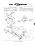
 Next
Next
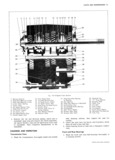
CLUTCH AND TRANSMISSIONS 7 2 MANUAL TRANSMISSIONS THREE SPEED TRANSMISSION INDEX Page Page General Description 7 2 Mainshaft 7 5 Transmission Assembly 7 2 Assembly 7 5 Disassembly of Case Components 7 2 Assembly of Case Components 7 6 Maillsh lft 7 2 Maintenance and Adjustments 7 G Disassembly 7 2 Side Cover Assembly 7 6 Cleaning and Inspection 7 3 Rgmgvgl 7 5 Transmission Case 7 3 Disassembly 7 6 Frenf wd Reer Bearings 7 3 Assembly 7 7 Bearing Rollers 7 4 Installation 7 7 G 9 1 S 4 7 4 Gearshift Control Assembly 7 7 Reverse Idler Geer Bushing 7 4 shim stack Selection 7 s R P8 l1 S 7 4 Shift Adjustment 7 9 Clutch Keys and Springs 7 4 Manual Transmission Removal 7 9 GENERAL DESCRIPTION In essence the Corvair manual three speed trans 2 Remove clutch gear bearing cover and gasket mission is a conventional synchromesh type except for 3 Remove clutch gear to bearing snap ring the use of concentric input and output shafts and its 4 Since the clutch gear bearing is a slip fit to both the mounting on the differential carrier clutch gear and case bore it may now be easily re Because of its attachment to the differential carrier moved from the case by tapping from inside the the mainshaft is hollow to permit passage of the clutch case with a brass drift used through the side cover shaft to the clutch gear at the front of the transmission opening The clutch gear drives a Oul lterge3 I and the remaining 5 Remove reverse idler gear retainer E ring and power flow sequence is identical to the conventional the rear bearing retainer strap ahd bolt Fig 2A three speed transmission 6 Remove rear bearing retainer mainshaft pilot bear In the transmission the shift rod carries a finger ings and clutch gear as an assembly out through which extends upward to engage either the first and re rear of case verse fork or the second and third fork located in the NOTE M h 1 f d cover depending on shift lever position As the two Ove Sync llomzell S QGVGS Orwlll as forks are parallel to each other a slight rotational mo necessary lo allow Clealallce between mamshall tion of the shift rod places the actuating finger in the and Coullleligear asS mbll S proper fork and permits the desired shift An interlock 7 Using a lohg drift through the eluteh gear bearing between the TWO ferk shafts h0ldS the fefk Het being case bore drive out the reverse idler shaft and its actuated in the neutral crossover position The reverse woodruff key Remove the reverse idler gear idler gear and shaft is retained by a woodruff key and an 8 Using Tool J 22246 and a plastic hammer drive the E rlllg The thrust washer betWeeIl the reverse idler eountershaft and its woodruff key out the rear of gear and case has been eliminated in the 1968 case Fig 3A Remove countergear roller bearings transmissions and tanged thrust washers through rear case bore The cover installed on the left hand side of the trans 9 If desired remove two screws and lock washers at mission is a casting with accommodations for internal taching shift finger to selector shaft and remove shift control components other than the selector shaft shaft out front of case Fig 4A and the selector The cover has a threaded through hole 10 The shaft seal may now be pryed from the case and in the area of the first and reverse shift fork and shaft replaced if necessary The backup lamp switch is installed in this hole and ac tuated by a ball when the shaft is in the reverse detent MAINSHAFT The same cover first and reverse shifter head and fork Disassembly Fig 6A ilisliglblx used as lust and S c0lld head to Shall lll 1 Using snap ring pliers remove the 2nd and 3rd g pins second and third shifter shaft used as third Speed Sliding Clutch hub Snap ring from mamshaft and fourth hdetent balls and detent springs are also used and I mOV Clutch assembly 2nd Speed blocker ring in the Corvair four speed transmission All drive gears have helical teeth and all forward and 2nd Speed gear from from Of m Sh 2 Remove rear bearing to mainshaft snap ring gears are Syllchllomzed 3 Support reverse gear with press plates J 9771 or i A SM SS ASSEMBLY 2 iY 2 a 5 S gsliezgisratziifi 5 g 3 I DISASSEMBLY OF CASE COMPONENTS washer rear bearing and bearing retainer assembly 4 Using snap ring pliers spread the rear bearing to 1 Remove side cover gasket and shift forks retainer snap ring and press bearing from retainer CORVAIR SHOP MANUAL SUPPLEMENT