Jeep Parts Wiki | Ford Parts Wiki
Home | Search | Browse
|
Corvair Chassis Shop Manual Supplement December 1967 |
|
Prev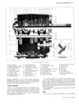
 Next
Next
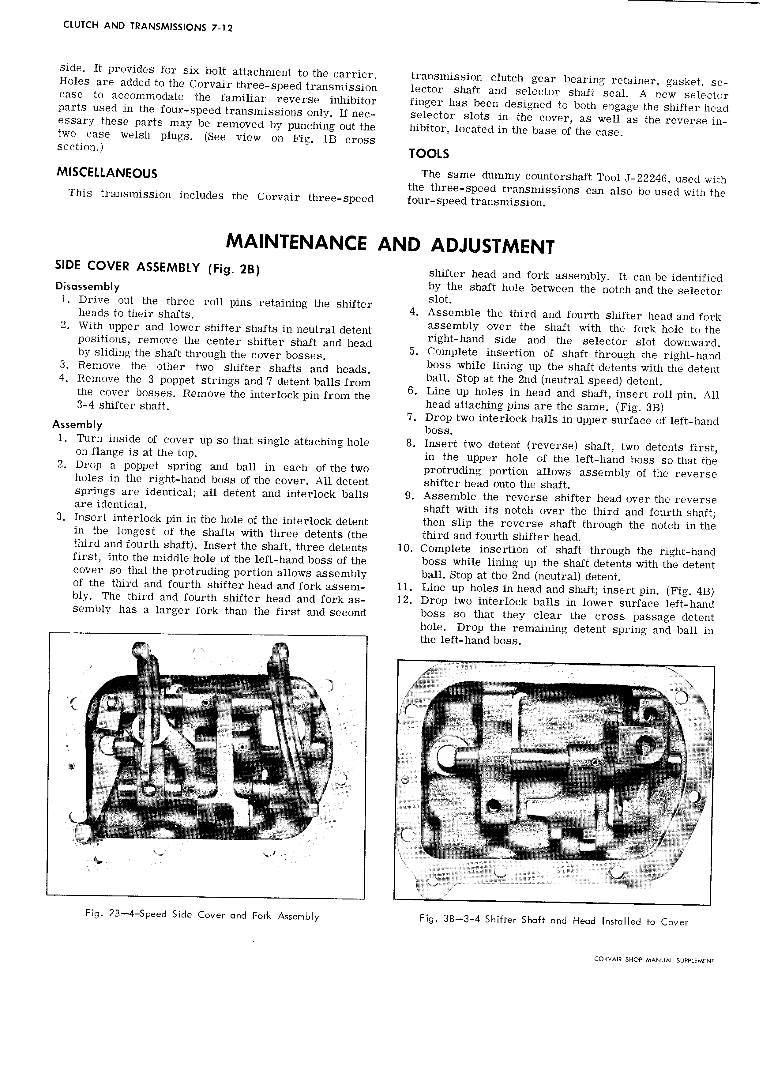
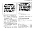
CLUTCH AND TRANSMISSIONS 7 12 side It provides for six bolt attachment to the carrier transmission clutch gear bearing retainer gasket se Holes are added t0 the Corvair three speed transmission lector shaft and selector shaft seal A new selector case to accommodate the familiar reverse inhibitor finger has been designed to both engage the shifter head parts used in the four speed transmissions only lf nec selector slots in the cover as well as the reverse in essary these parts may be removed by punching out the hibitor located in the base of the case two case welsh plugs See view on Fig 1B cross section TOOLS MISCELLANEOUS The same dummy countershaft Tool J 22246 used with the three speed transmissions can also be used with the This transmission includes the Corvair three speed four speed transmission SIDE COVER ASSEMBLY Fig 2B shifter head and fork assembly It can be identified Disassembly gyctthe shaft hole between the notch and the selector l D t t l h tgutheigesggiie ml pms mtmmng the Shlfter 4 Assemble the third and fourth shifter head and fork 2 With upper and lower shifter shafts in neutral detent a S mb1y OVET the Shaft with the fork hO1 tO the right hand side and the selector slot downward positions remove the center shifter shaft and head b 5 Complete insertion of shaft through the r1ght nand y sliding the shaft through the cover bosses boss while lining up the shaft detents with the detent 3 Remove the other two shifter shafts and heads ball Stop at the 2nd neutral speed detent 4 Remove the 3 poppet strings and 7 detent balls from 6 Line up holes in head and shaft insert roll pin All the cover bosses Remove the interlock pin from the 3 4 Shifter Shaft head attaching pins are the same Fig 3B 7 Drop two interlock balls in upper surface of left hand Assembly boss 1 Turn inside of cover up so that single attaching hole 8 Insert two detent reverse shaft two detents first on flange is at the top in the upper hole of the left hand boss so that the 2 Drop a poppet spring and ball in each of the two protruding portion allows assembly of the reverse holes in the right hand boss of the cover All detent shifter head onto the shaft springs are identical all detent and interlock balls 9 Assemble the reverse shifter head over the reverse are identical shaft with its notch over the third and fourth shaft 3 Insert interlock pin in the hole of the interlock detent then slip the reverse shaft through the notch in the in the longest of the shafts with three detents the third and fourth shifter head third and fourth shaft Insert the shaft three detents 10 Complete insertion of shaft through the right hand first into the middle hole of the left hand boss of the boss while lining up the shaft detents with the detent cover so that the protruding portion allows assembly ball Stop at the 2nd neutral detent of the third and fourth shifter head and fork assem 11 Line up holes in head and shaft insert pin Fig 4B bly The third and fourth shifter head and fork as 12 Drop two interlock balls in lower surface left hand sembly has a larger fork than the first and second boss so that they clear the cross passage detent hole Drop the remaining detent spring and ball in the left hand boss M y W t E iitt re t 3ii t s if itst i I V i I I itit lteci 45 V r ti i l I I stts t i J i i t i E l a liii it I i i i 1 sss t T I iti Cf lt si i W ca l i t i tL L 3 r3 3 3 Ls ti Q by 3 gill I k ty c M M c c t lf xg V r Fig 2B 4 Speecl Side Cover and Fork Assembly Fig 3B 3 4 Shifter Shaft and Head Installed to Cover COR AIR SHOP MANUAL SUPPLEMENT