Jeep Parts Wiki | Ford Parts Wiki
Home | Search | Browse | Marketplace | Messages | FAQ | Guest
|
Corvair Chassis Shop Manual December 1964 |
|
Prev

 Next
Next
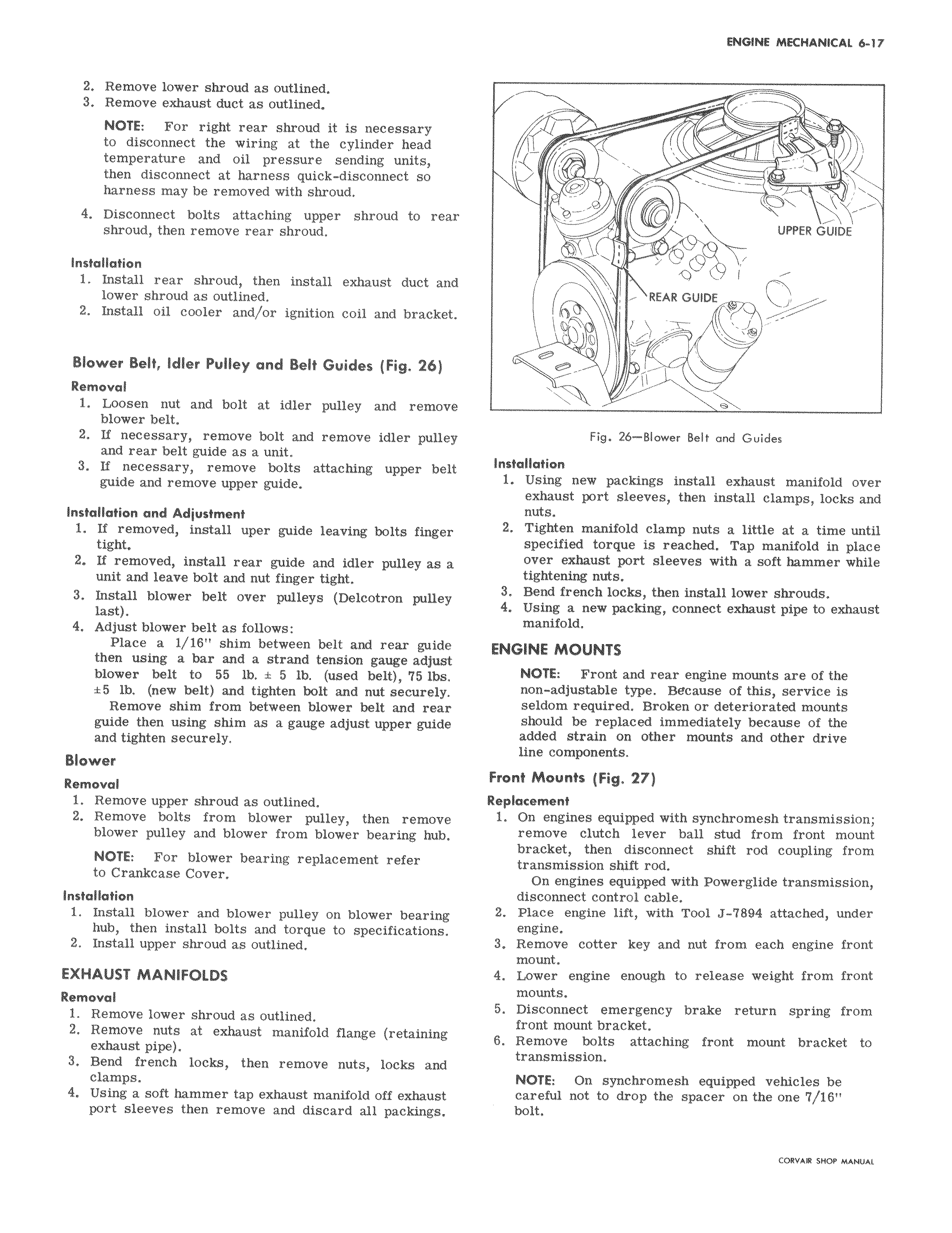
2 Remove lower shroud as outlined 3 Remove exhaust duct as outlined NOTE For right rear shroud it is necessary to disconnect the wiring at the cylinder head temperature and oil pressure sending units then disconnect at harness quick disconnect so harness may be removed with shroud 4 Disconnect bolts attaching upper shroud to reaz shroud then remove rear shroud Installation 1 Install rear shroud then install exhaust duct and lower shroud as outlined 2 Install oil cooler and or ignition coil and bracket Blower Belt Idler Pulley and Belt Guides Fig 26 Removal 1 Loosen nut and bolt at idler pulley and removt blower belt 2 If necessary remove bolt and remove idler pulle and rear belt guide as a unit 3 If necessary remove bolts attaching upper bell guide and remove upper guide Installation and Adjustment 1 If removed install uper guide leaving bolts finger tight 2 If removed install rear guide and idler pulley as a unit and leave bolt and nut finger tight 3 Install blower belt over pulleys Delcotron pulley last 4 Adjust blower belt as follows Place a 1 16 shim between belt and rear guide then using a bar and a strand tension gauge adjust blower belt to 55 lb t 5 lb used belt 75 Ibs t 5 lb new belt and tighten bolt and nut securely Remove shim from between blower belt and rear guide then using shim as a gauge adjust upper guide and tighten securely Blower Removal 1 Remove upper shroud as outlined 2 Remove bolts from blower pulley then remove blower pulley and blower from blower bearing hub NOTE For blower bearing replacement refer to Crankcase Cover Installation 1 Install blower and blower pulley on blower bearing hub then install bolts and torque to specifications 2 Install upper shroud as outlined EXHAUST MANIFOLDS Removal 1 Remove lower shroud as outlined 2 Remove nuts at exhaust manifold flange retaining exhaust pipe 3 Bend french locks then remove nuts locks and clamps 4 Using a soft hammer tap exhaust manifold off exhaust port sleeves then remove and discard all packings Is 1 w UPPER GUIDE REAR GUIDE 1 Fig 26 Blower Belt and Guides Installation 1 Using new packings install exhaust manifold over exhaust port sleeves then install clamps locks and nuts 2 Tighten manifold clamp nuts a little at a time until specified torque is reached Tap manifold in place over exhaust port sleeves with a soft hammer while tightening nuts 3 Bend french locks then install lower shrouds 4 Using a new packing connect exhaust pipe to exhaust manifold ENGINE MOUNTS NOTE Front and rear engine mounts are of the non adjustable type Because of this service is seldom required Broken or deteriorated mounts should be replaced immediately because of the added strain on other mounts and other drive line components Front Mounts Fig 27 Replacement 1 On engines equipped with synchromesh transmission remove clutch lever ball stud from front mount bracket then disconnect shift rod coupling from transmission shift rod On engines equipped with Powerglide transmission disconnect control cable 2 Place engine lift with Tool J 7894 attached under engine 3 Remove cotter key and nut from each engine front mount 4 Lower engine enough to release weight from front mounts 5 Disconnect emergency brake return spring from front mount bracket 6 Remove bolts attaching front mount bracket to transmission NOTE On synchromesh equipped vehicles be careful not to drop the spacer on the one 7 16 bolt CORVAR SHOP MANUAL

 Next
Next