Jeep Parts Wiki | Ford Parts Wiki
Home | Search | Browse
|
Corvair Chassis Shop Manual December 1964 |
|
Prev

 Next
Next
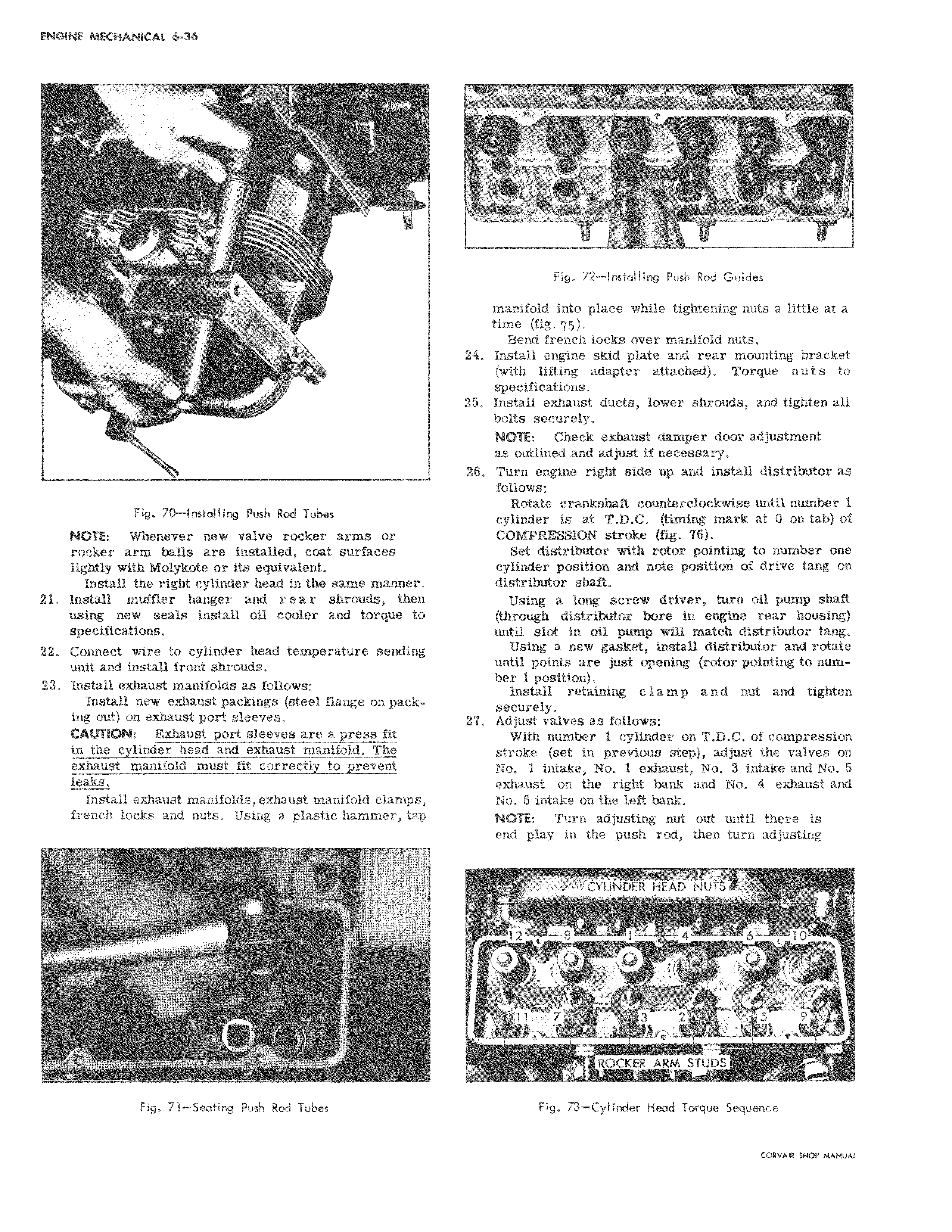
A Vr F v Fig 70 Installing Push Rod Tubes NOTE Whenever new valve rocker arms or rocker arm balls are installed coat surfaces lightly with Molykote or its equivalent Install the right cylinder head in the same manne 21 Install muffler hanger and r e a r shrouds the using new seals install oil cooler and torque tb specifications I 22 Connect wire to cylinder head temperature sending unit and install front shrouds 23 Install exhaust manifolds as follows Install new exhaust packings steel flange on pac Iing out on exhaust port sleeves CAUTION Exhaust port sleeves are a press fit in the cylinder head and exhaust manifold The exhaust manifold must fit correctly to prevent leaks I Install exhaust manifolds exhaust manifold clamp french locks and nuts Using a plastic hammer t p 1 Fig 71 Seating Push Rod Tubes I 1 L Fig 72 Installing push Rod Guides manifold into place while tightening nuts a little at a time fig q5 Bend french locks over manifold nuts 24 Install engine skid plate and rear mounting bracket with lifting adapter attached Torque nuts to specifications 25 Install exhaust ducts lower shrouds and tighten all bolts securely NOTE Check exhaust damper door adjustment as outlined and adjust if necessary 28 Turn engine right side up and install distributor as follows Rotate crankshaft counterclockwise until number 1 cylinder is at T D C timing mark at 0 on tab of COMPRESSION stroke fig 76 et distributor with rotor pointing to number one cylinder position and note position of drive tang on distributor shaft Using a long screw driver turn oil pump shaft through distributor bore in engine rear housing until slot in oil pump will match distributor tang Using a new gasket install distributor and rotate until points are just opening rotor pointing to number 1 position Gnstall retaining clamp and nut and tighten seCurely 27 Adjust valves as follows With number 1 cylinder on T D C of compression stroke set in previous step adjust the valves on No 1 intake No 1 exhaust No 3 intake and No 5 exiaust on the right bank and No 4 exhaust and No 6 intake on the left bank NOTE Turn adjusting nut out until there is end play in the push rod then turn adjusting CYLINDER HEAD NUTS 1 8 1 4 10 BUQ 1 11 7 3 2 y 4 5 q o e c RCKKHt ARM STUDS Fig 73 Cylinder Head Torque Sequence CORVAR SHOP MANUAL

 Next
Next