Jeep Parts Wiki | Ford Parts Wiki
Home | Search | Browse
|
Corvair Chassis Shop Manual December 1964 |
|
Prev
 Next
Next
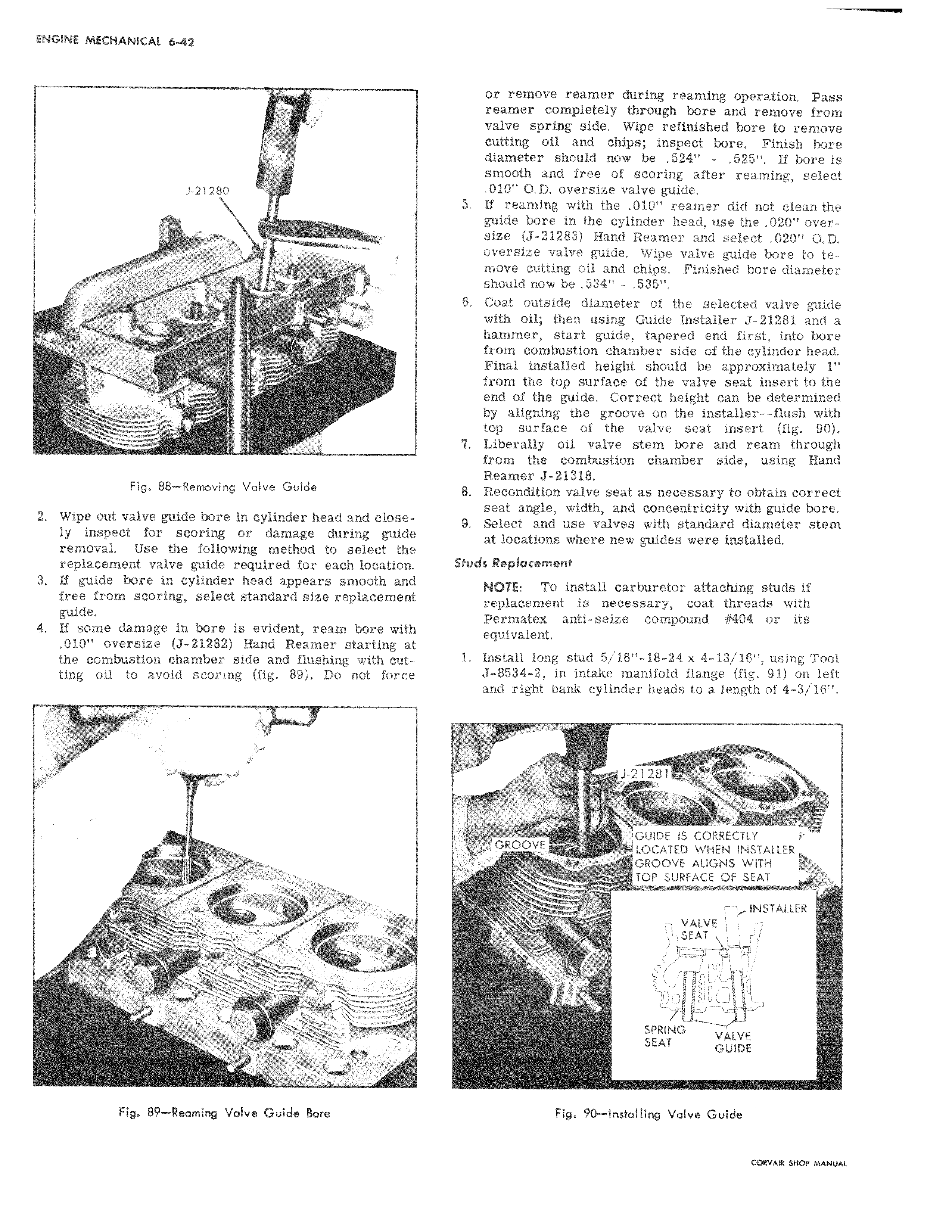
x r J v n Y h I i r 4 144 or remove reamer during reaming operation Pass reamer completely through bore and remove from valve spring side Wipe refinished bore to remove cutting oil and chips inspect bore Finish bore diamOter should now be 524 525 If bore is smooth and free of scoring after reaming select 010 O D oversize valve guide b If reaming with the 010 reamer did not clean the guide bore in the cylinder head use the 020 oversize J 21283 Hand Reamer and select 020 O D oversize valve guide Wipe valve guide bore to temove cutting oil and chips Finished bore diameter should now be 534 535 6 Coat outside diameter of the selected valve guide with oil then using Guide Installer J 21281 and a hammer start guide tapered end first into bore from combustion chamber side of the cylinder head Final installed height should be approximately 1 from the top surface of the valve seat insert to the end of the guide Correct height can be determined by aligning the groove on the installer flush with top surface of the valve seat insert fig 90 7 Liberally oil valve stem bore and ream through from the combustion chamber side using Hand Reamer J 21318 8 Recondition valve seat as necessary to obtain correct seat angle width and concentricity with guide bore 9 Select and use valves with standard diameter stem at locations where new guides were installed Studs Replacement NOTE To install carburetor attaching studs if replacement is necessary coat threads with Permatex anti seize compound 404 or its equivalent 1 Install long stud 5 16 18 24 x 4 13 16 using Tool J 8584 2 in intake manifold flange fig 91 on left and right bank cylinder heads to a length of 4 3 16 J 21281 f x r GRIDOVE GUIDE IS CORRECTLY LOCATED WHEN INSTALLER R GROOVE ALIGNS WITH TOP SURFACE OF SEAT r lr INSTALLER VALVE SEAT 77 v y1 SPRING SEAT VALVE GUIDE Fig 90 Installing Volve Guide riwi r e u e