Jeep Parts Wiki | Ford Parts Wiki
Home | Search | Browse
|
Corvair Chassis Shop Manual December 1964 |
|
Prev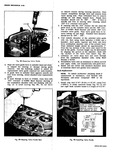
 Next
Next
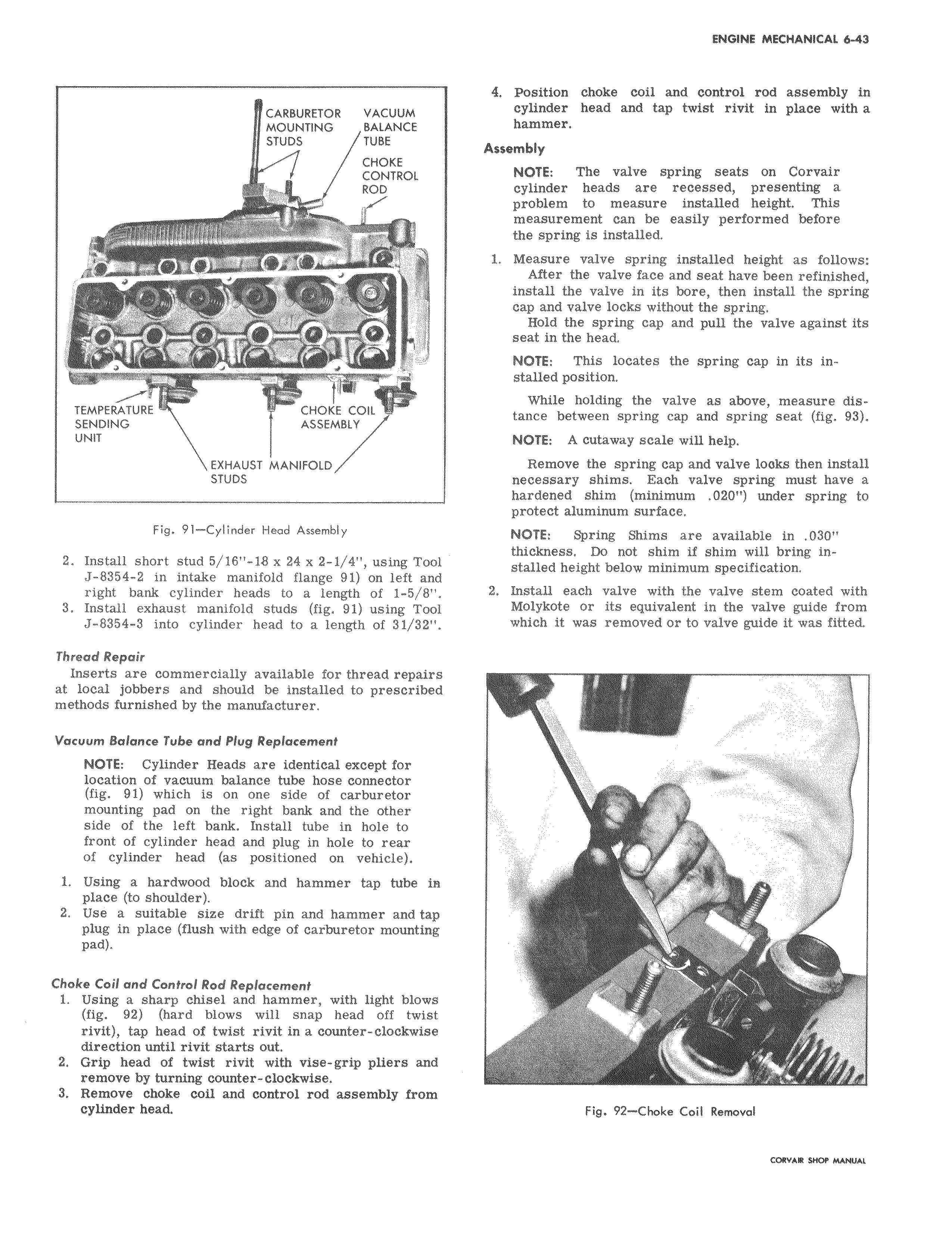
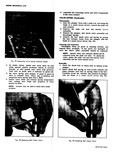
CARBURETOR VACUUM MOUNTING BALANCE STUDS TUBE CHOKE CONTROL ROD J J i 0 A COIL CHOK E CO IL SENDING ASSEMBLY UNIT EXHAUST MANIFOLD STUDS Fig 91 Cylinder Head Assembly 2 Install short stud 5 16 18 x 24 x 2 1 4 using Tool J 8354 2 in intake manifold flange 91 on left and right bank cylinder heads to a length of 1 5 8 3 Install exhaust manifold studs fig 91 using Tool J 8354 3 into cylinder head to a length of 31 32 Thread Repair Inserts are commercially available for thread repairs at local jobbers and should be installed to prescribed methods furnished by the manufacturer Vacuum Balance Tube and Plug Replacement NOTE Cylinder Heads are identical except for location of vacuum balance tube hose connector fig 91 which is on one side of carburetor mounting pad on the right bank and the other side of the left bank Install tube in hole to front of cylinder head and plug in hole to rear of cylinder head as positioned on vehicle 1 Using a hardwood block and hammer tap tube in place to shoulder 2 Use a suitable size drift pin and hammer and tap plug in place flush with edge of carburetor mounting pad Choke Coil and Control Rod Replacement 1 Using a sharp chisel and hammer with light blows fig 92 hard blows will snap head off twist rivit tap head of twist rivit in a counter clockwise direction until rivft starts out 2 Grip head of twist rivit with vise grip pliers and remove by turning counter clockwise 3 Remove choke coil and control rod assembly from cylinder head 4 Position choke coil and control rod assembly in cylinder head and tap twist rivit in place with a hammer Assembly NOTE The valve spring seats on Corvair cylinder heads are recessed presenting a problem to measure installed height This measurement can be easily performed before the spring is installed 1 Measure valve spring installed height as follows After the valve face and seat have been refinished install the valve in its bore then install the spring cap and valve locks without the spring Hold the spring cap and pull the valve against its seat in the head NOTE This locates the spring cap in its installed position While holding the valve as above measure distance between spring cap and spring seat fig 93 NOTE A cutaway scale will help Remove the spring cap and valve looks then install necessary shims Each valve spring must have a hardened shim minimum 020 under spring to protect aluminum surface NOTE Spring Shims are available in 030 thickness Do not shim if shim will bring installed height below minimum specification 2 Install each valve with the valve stem coated with Molykote or its equivalent in the valve guide from which it was removed or to valve guide it was fitted J I rr i Fig 92 Choke Coil Removal tatvwe sHOr Mawru