Jeep Parts Wiki | Ford Parts Wiki
Home | Search | Browse
|
Corvair Chassis Shop Manual December 1964 |
|
Prev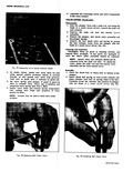

 Next
Next
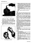
e DRIFT PIN OIL FEED HOLE yie DRIFT PIN Fig 96 Assembling the Hydraulic Lifter 3 Place the plunger spring over the ball retainer and slide the lifter body over the spring and plunger being careful to line up the oil feed holes in the lifter body and plunger 4 Fill the assembly with SAE 10 oil then insert the end of a 1 8 drift pin into the plunger and press down solid At this point oil holes in the lifter body and plunger assembly will be aligned fig 98 CAUTION Do not attempt to force or pump the plunger 5 Insert a 1 16 drift pin through both oil holes to hold the plunger down against the lifter spring tension fig 96 NOTE The drift pin must not extend inside the plunger 6 Remove the 1 8 drift pin refill assembly with SAE 10 oil 7 Install the push rod seat and inertia valve assembly 8 Install the push rod seat retainer press down on the push rod seat and remove the 1 16 drift pin from the oil holes The lifter is now completely assembled filled with oil and ready for installation CYLINDER PISTON AND CONNECTING ROD ASSEMBLIES Disassembly 1 Remove piston assembly from cylinder by pushing piston through cylinder with the end of a hammer handle fig 97 2 Remove all piston rings by expanding them and sliding them off the top of the pistons Tool J 8018 is available for this purpose 3 Install piston and connecting rod assembly on support J 6994 1 and Adapter J 8355 1 Place assembly 1 I r X ed t F w v s m m n INSTALLER 46 ADAPTER SUPPORT