Jeep Parts Wiki | Ford Parts Wiki
Home | Search | Browse
|
Corvair Chassis Shop Manual December 1964 |
|
Prev
 Next
Next
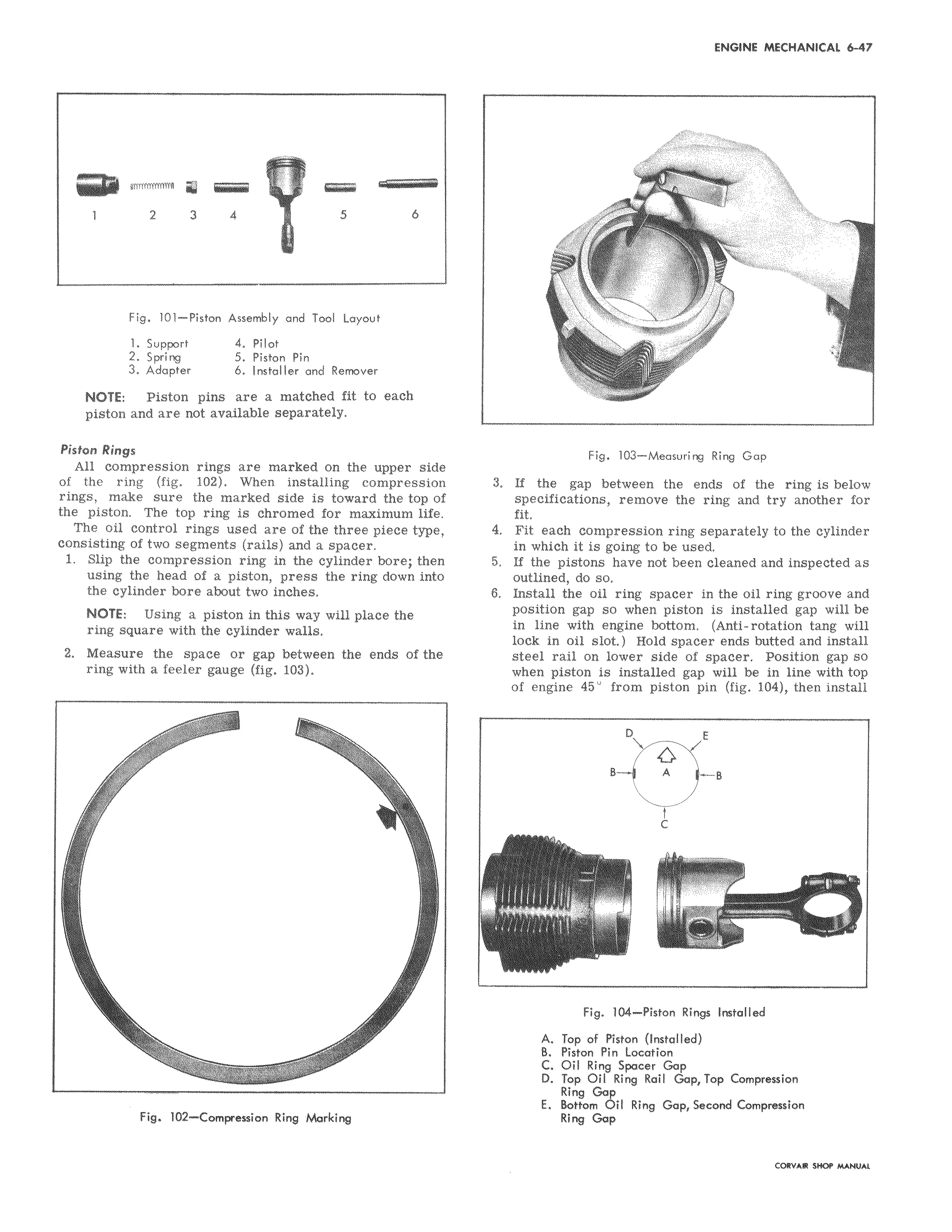
1 2 3 4 5 6 Fig 101 Piston Assembly and Tool Layout 1 Support 4 Pilot 2 Spring 5 Piston Pin 3 Adapter b Installer and Remover NOTE Piston pins are a matched fit to each piston and are not available separately Piston Rings All compression rings are marked on the upper side of the ring fig 102 When installing compression rings make sure the marked side is toward the top of the piston The top ring is chromed for maximum life The oil control rings used are of the three piece type consisting of two segments rails and a spacer 1 Slip the compression ring in the cylinder bore then using the head of a piston press the ring down into the cylinder bore about two inches NOTE Using a piston in this way will place the ring square with the cylinder walls 2 Measure the space or gap between the ends of the ring with a feeler gauge fig 103 Fig 102 Compression Ring Marking x J Fig 103 Measuring Ring Gap 3 If the gap between the ends of the ring is below specifications remove the ring and try another for fit 4 Fit each compression ring separately to the cylinder in which it is going to be used 5 If the pistons have not been cleaned and inspected as outlined do so 6 Install the oil ring spacer in the oil ring groove and position gap so when piston is installed gap will be in line with engine bottom Anti rotation tang will lock in oil slot Hold spacer ends butted and install steel rail on lower side of spacer Position gap so when piston is installed gap will be in line with top of engine 45 from piston pin fig 104 then install D E B A g C r Fig 104 Piston Rings Installed A Top of Piston Installed B Piston Pin Location C Oil Ring Spacer Gap D Top Oil Ring Rail GapTop Compression Ring Gap E Bottom Oil Ring Gap Second Compression Ring Gap