Jeep Parts Wiki | Ford Parts Wiki
Home | Search | Browse
|
Corvair Chassis Shop Manual December 1964 |
|
Prev

 Next
Next
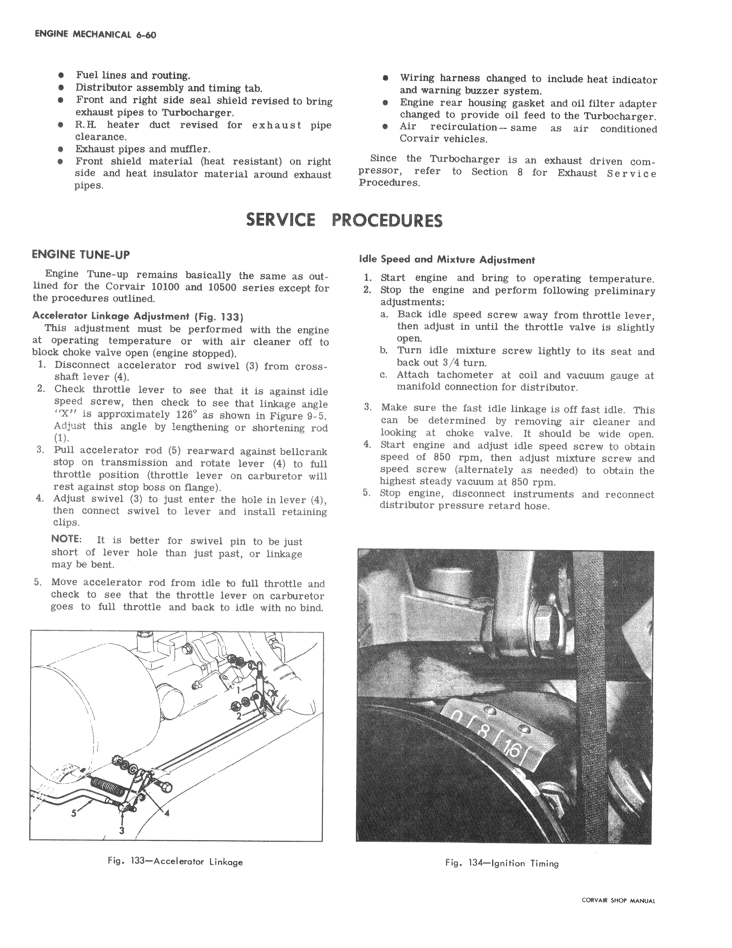
Fuel lines and routing Distributor assembly and timing tab Front and right side seal shield revised to bring exhaust pipes to Turbocharger e R Ii heater duct revised for exhaust pip e clearance Exhaust pipes and muffler I Front shield material heat resistant on right side and heat insulator material around exhaust pipes SERVICE PR ENGINE TUNE UP Engine Tune up remains basically the same as out lined for the Corvair 10100 and 10500 series exceptfo the procedures outlined Accelerator Linkage Adjustment Fig 133 This adjustment must be performed with the engine at operating temperature or with air cleaner off t block choke valve open engine stopped 1 Disconnect accelerator rod swivel 3 from cross shaft lever 4 2 Check throttle lever to see that it is against idle speed screw then check to see that linkage 79 Adjust X is approximately 126 as shown in Figure 9 5 Adjust this angle by lengthening or shortening ro 1 3 Pull accelerator rod 5 rearward against bellerank stop on transmission and rotate lever 4 to full throttle position throttle lever on carburetor will rest against stop boss on flange 4 Adjust swivel 3 to just enter the hole in lever 4 then connect swivel to lever and install retaining clips NOTE It is better for swivel pin to be just short of lever hole than just past or linkage may be bent 5 Move accelerator rod from idle to full throttle and I check to see that the throttle lever on carburetor goes to full throttle and back to idle with no bind J r s p s 3 Fig 133 Accelerator Linkage wViring harness changed to include heat indicator and warning buzzer system e Engine rear housing gasket and oil filter adapter changed to provide oil feed to the Turbocharger Air recirculation same as air conditioned Corvair vehicles Since the Turbocharger is an exhaust driven compressor refer to Section 8 for Exhaust S e r v i c e Procedures OCEDURES Idle Speed and Mixture Adjustment 1 Start engine and bring to operating temperature 2 Stop the engine and perform following preliminary adjustments a Back idle speed screw away from throttle lever then adjust in until the throttle valve is slightly capen b turn idle mixture screw lightly to its seat and b I ack out 3 4 turn c Attach tachometer at coil and vacuum gauge at manifold connection for distributor 3 Make sure the fast idle linkage is off fast idle This can be determined by removing air cleaner and looking at choke valve It should be wide open 4 Stark engine and adjust idle speed screw to obtain speed of 850 rpm then adjust mixture screw and speed screw alternately as needed to obtain the highest steady vacuum at 850 rpm 5 Stop engine disconnect instruments and reconnect dist4ibutor pressure retard hose yf r f x r Fig 134 Ignition Timing

 Next
Next