Jeep Parts Wiki | Ford Parts Wiki
Home | Search | Browse
|
Corvair Chassis Shop Manual December 1964 |
|
Prev
 Next
Next
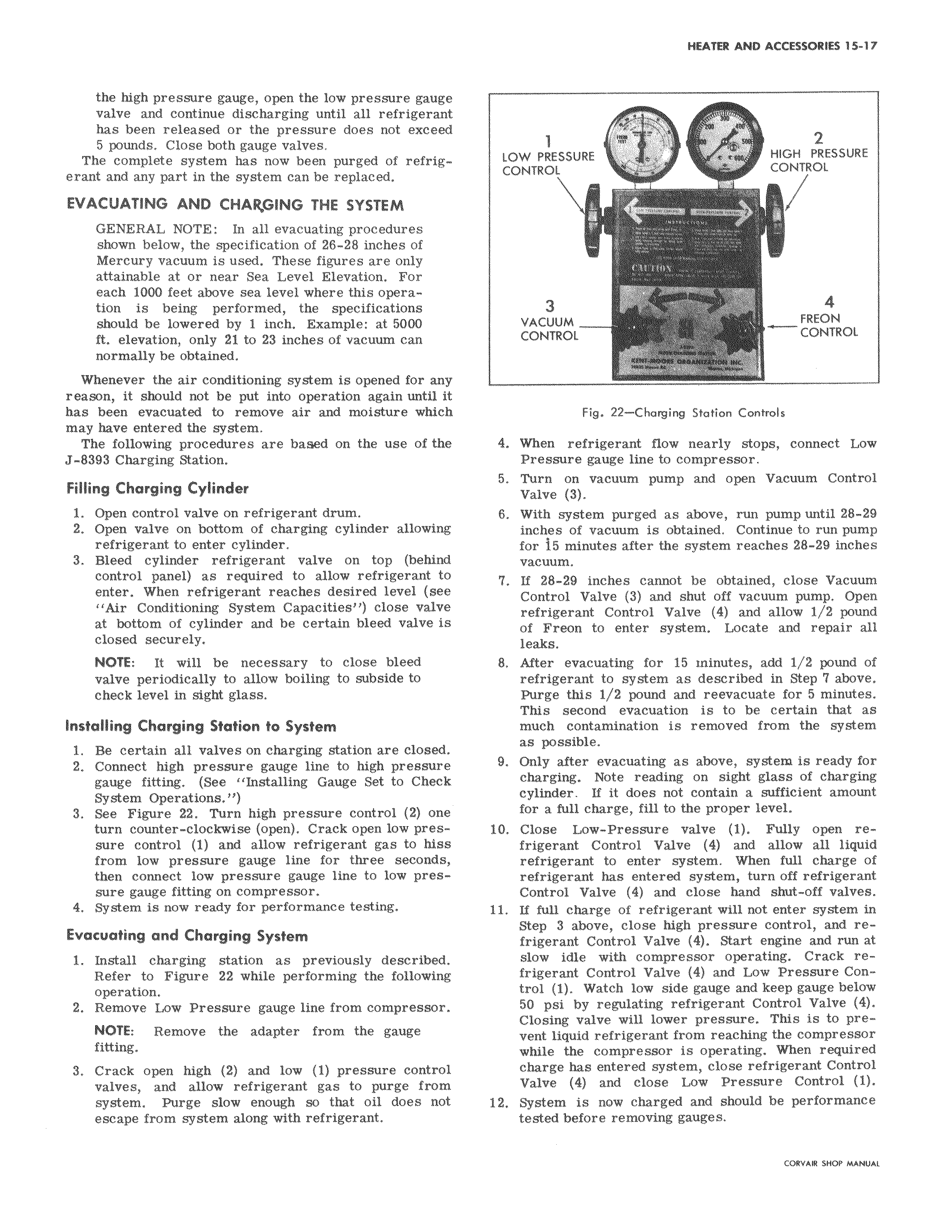
the high pressure gauge open the low pressure gauge valve and continue discharging until all refrigerant has been released or the pressure does not exceed 5 pounds Close both gauge valves The complete system has now been purged of refrigerant and any part in the system can be replaced EVACUATING AND CHARGING THE SYSTEM GENERAL NOTE In all evacuating procedures shown below the specification of 26 28 inches of Mercury vacuum is used These figures are only attainable at or near Sea Level Elevation For each 1000 feet above sea level where this operation is being performed the specifications should be lowered by 1 inch Example at 5000 ft elevation only 21 to 23 inches of vacuum can normally be obtained Whenever the air conditioning system is opened for any reason it should not be put into operation again until it has been evacuated to remove air and moisture which may have entered the system The following procedures are based on the use of the J 8393 Charging Station Filling Charging Cylinder 1 Open control valve on refrigerant drum 2 Open valve on bottom of charging cylinder allowing refrigerant to enter cylinder 3 Bleed cylinder refrigerant valve on top behind control panel as required to allow refrigerant to enter When refrigerant reaches desired level see Air Conditioning System Capacities close valve at bottom of cylinder and be certain bleed valve is closed securely NOTE It will be necessary to close bleed valve periodically to allow boiling to subside to check level in sight glass Installing Charging Station to System 1 Be certain all valves on charging station are closed 2 Connect high pressure gauge line to high pressure gauge fitting See Installing Gauge Set to Check System Operations 3 See Figure 22 Turn high pressure control 2 one turn counter clockwise open Crack open low pressure control 1 and allow refrigerant gas to hiss from low pressure gauge line for three seconds then connect low pressure gauge line to low pressure gauge fitting on compressor 4 System is now ready for performance testing Evacuating and Charging System 1 Install charging station as previously described Refer to Figure 22 while performing the following operation 2 Remove Low Pressure gauge line from compressor NOTE Remove the adapter from the gauge fitting 3 Crack open high 2 and low 1 pressure control valves and allow refrigerant gas to purge from system Purge slow enough so that oil does not escape from system along with refrigerant 1 2 LOW PRESSURE HIGH PRESSURE CONTROL CONTROL 3 4 VACUUM FREON CONTROL CONTROL Fig 22 Charging Station Controls 4 When refrigerant flow nearly stops connect Low Pressure gauge line to compressor 5 Turn on vacuum pump and open Vacuum Control Valve 3 6 With system purged as above run pump until 28 29 inches of vacuum is obtained Continue to run pump for 15 minutes after the system reaches 28 29 inches vacuum 7 If 28 29 inches cannot be obtained close Vacuum Control Valve 3 and shut off vacuum pump Open refrigerant Control Valve 4 and allow 1 2 pound of Freon to enter system Locate and repair a11 leaks 8 After evacuating for 15 minutes add 1 2 pound of refrigerant to system as described in Step 7 above Purge this 1 2 pound and reevacuate for 5 minutes This second evacuation is to be certain that as much contamination is removed from the system as possible 9 Only after evacuating as above system is ready for charging Note reading on sight glass of charging cylinder If it does not contain a sufficient amount for a full charge fill to the proper level 10 Close Low Pressure valve 1 Fully open refrigerant Control Valve 4 and allow all liquid refrigerant to enter system When full charge of refrigerant has entered system turn off refrigerant Control Valve 4 and close hand shut off valves 11 If full charge of refrigerant will not enter system in Step 3 above close high pressure control and refrigerant Control Valve 4 Start engine and run at slow idle with compressor operating Crack refrigerant Control Valve 4 and Low Pressure Control 1 Watch low side gauge and keep gauge below 50 psi by regulating refrigerant Control Valve 4 Closing valve will lower pressure This is to prevent liquid refrigerant from reaching the compressor while the compressor is operating When required charge has entered system close refrigerant Control Valve 4 and close Low Pressure Control 1 12 System is now charged and should be performance tested before removing gauges rrov o curo u wu