Jeep Parts Wiki | Ford Parts Wiki
Home | Search | Browse
|
Corvair Chassis Shop Manual December 1964 |
|
Prev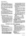
 Next
Next
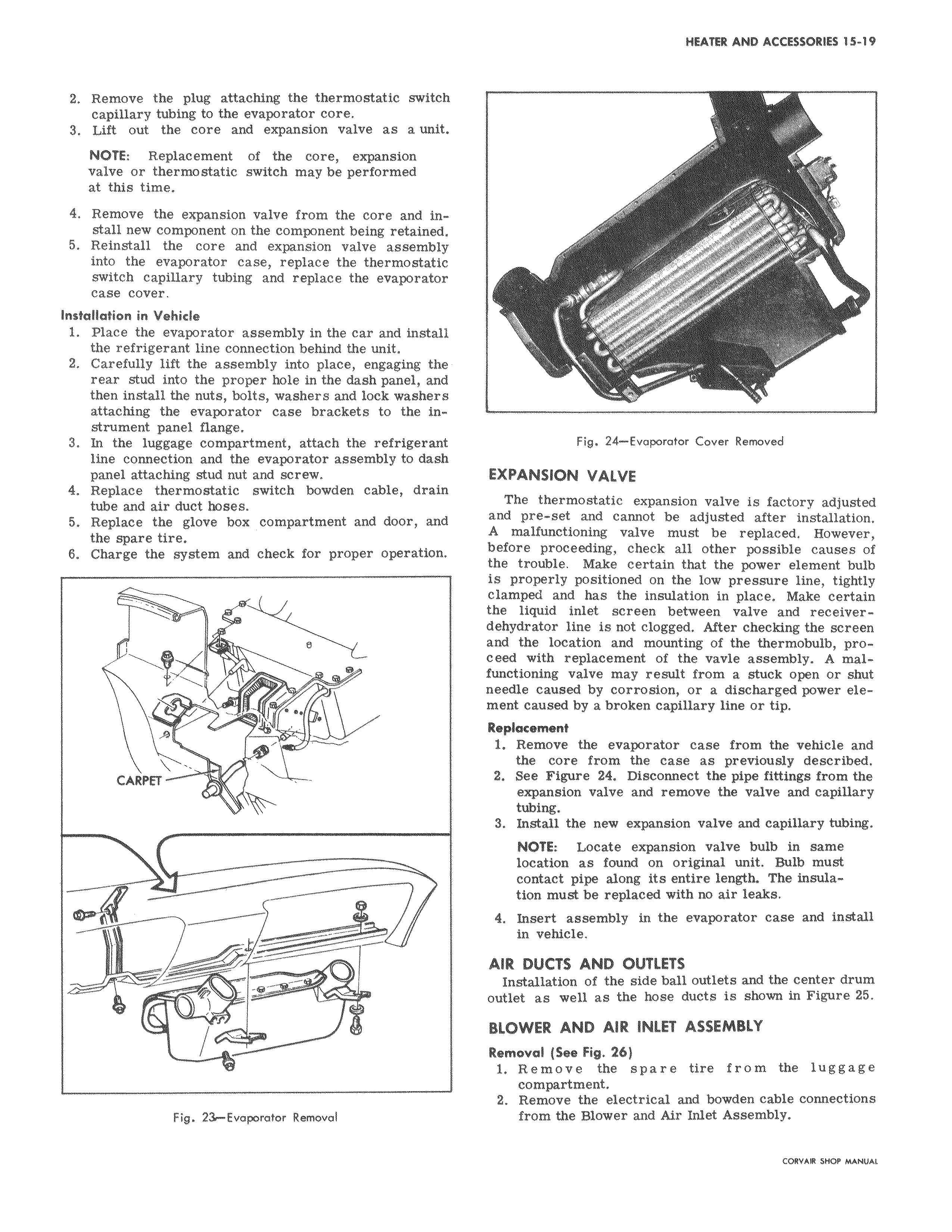
2 Remove the plug attaching the thermostatic switch capillary tubing to the evaporator core 3 Lift out the core and expansion valve as a unit NOTE Replacement of the core expansion valve or thermostatic switch may be performed at this time 4 Remove the expansion valve from the core and install new component on the component being retained 5 Reinstall the core and expansion valve assembly into the evaporator case replace the thermostatic switch capillary tubing and replace the evaporator case cover Insfallation in Vehicle 1 Place the evaporator assembly in the car and install the refrigerant line connection behind the unit 2 Carefully lift the assembly into place engaging the rear stud into the proper hole in the dash panel and then install the nuts bolts washers and lock washers attaching the evaporator case brackets to the instrument panel flange 3 In the luggage compartment attach the refrigerant line connection and the evaporator assembly to dash panel attaching stud nut and screw 4 Replace thermostatic switch bowden cable drain tube and air duct hoses 5 Replace the glove box compartment and door and the spare tire 6 Charge the system and check for proper operation e CARPEf f Fig 23 Evaporator Removal r r f 1000 Fig 24 Evaporator Cover Removed EXPANSION VALVE The thermostatic expansion valve is factory adjusted and pre set and cannot be adjusted after installation A malfunctioning valve must be replaced However before proceeding check all other possible causes of trouble w er element bulb is properly positioned on the low pressure line tightly clamped and has the insulation in place Make certain receiver dehydrator r line is not clogged After checking the screen location mounting W proceed malfunctioning ning valve may result from a stuck open or shut needle caused corrosion power element nt caused by a broken capillary line or tip 1 Remove the evaporator case from the vehicle and the core from the case as previously described 2 See Figure 24 Disconnect the pipe fittings from the expansion valve and remove valve and capillary 3 Install the new expansion valve and capillary tubing NOTE Locate expansion valve bulb in same location as found on original unit Bulb must pipe along entire length The insulation n must be replaced with no air leaks 4 Insert assembly in the evaporator case and install Installation of the side ball outlets and the center drum outlet as well as the hose ducts is shown in Figure 25 Remove ve the spare tire from the luggage compartment 2 Remove the electrical and bowden cable connections in vehicle AIR DUCTS AND OUTLETS BLOWER AND AIR INLET ASSEMBLY Removal See Fig 26 W Blower Inlet Assembly Air