Jeep Parts Wiki | Ford Parts Wiki
Home | Search | Browse
|
Corvair Chassis Shop Manual December 1964 |
|
Prev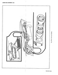
 Next
Next
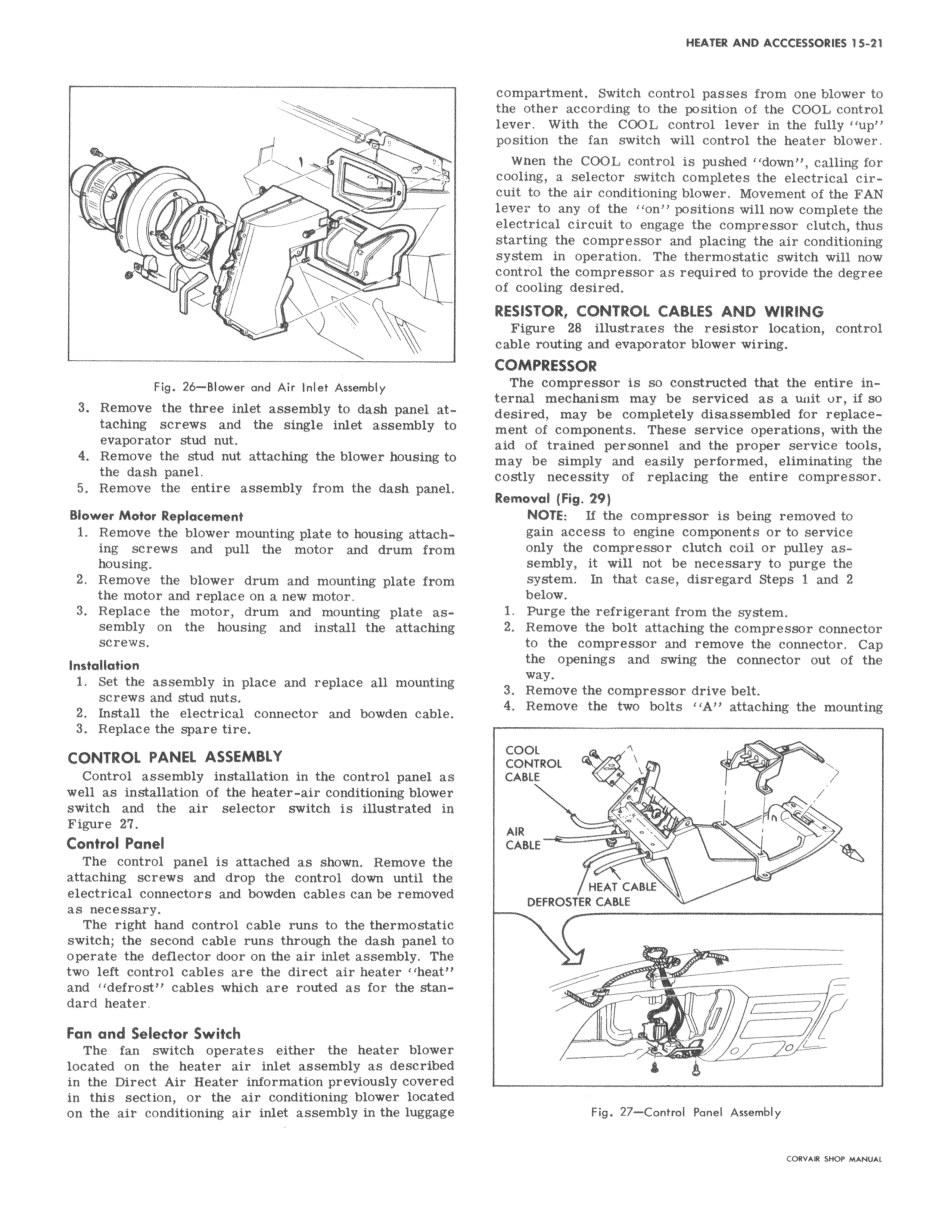
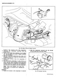
s m i Fig 26 Blower and Air Inlet Assembly 3 Remove the three inlet assembly to dash panel at taching screws and the single inlet assembly tC evaporator stud nut 4 Remove the stud nut attaching the blower housing tc the dash panel 5 Remove the entire assembly from the dash panel Blower Motor Replacement 1 Remove the blower mounting plate to housing attaching screws and pull the motor and drum from housing 2 Remove the blower drum and mounting plate from the motor and replace on a new motor 3 Replace the motor drum and mounting plate assembly on the housing and install the attaching screws Installation 1 Set the assembly in place and replace all mounting screws and stud nuts 2 Install the electrical connector and bowden cable 3 Replace the spare tire CONTROL PANEL ASSEMBLY Control assembly installation in the control panel as well as installation of the heater air conditioning blower switch and the air selector switch is illustrated in Figure 27 Control Panel The control panel is attached as shown Remove the attaching screws and drop the control down until the electrical connectors and bowden cables can be removed as necessary The right hand control cable runs to the thermostatic switch the second cable runs through the dash panel to operate the deflector door on the air inlet assembly The two left control cables are the direct air heater heat and defrost cables which are routed as for the standard heater Fan and Selector Switch The fan switch operates either the heater blower located on the heater air inlet assembly as described in the Direct Air Heater information previously covered in this section or the air conditioning blower located on the air conditioning air inlet assembly in the luggage compartment Switch control passes from one blower to the other according to the position of the COOL control lever With the COOL control lever in the fully up position the fan switch will control the heater blower When the COOL control is pushed down calling for cooling a selector switch completes the electrical circuit to the air conditioning blower Movement of the FAN lever to any of the on positions will now complete the electrical circuit to engage the compressor clutch thus starting the compressor and placing the air conditioning system in operation The thermostatic switch will now control the compressor as required to provide the degree of cooling desired RESISTOR CONTROL CABLES AND WIRING i Figure 28 illustrates the resistor location control cable routing and evaporator blower wiring COMPRESSOR The compressor is so constructed that the entire internal mechanism may be serviced as a unit ur if so desired may be completely disassembled for replace ment of components These service operations with the aid of trained personnel and the proper service tools may be simply and easily performed eliminating the costly necessity of replacing the entire compressor Removal Fig 29 NOTE If the compressor is being removed to gain access to engine components or to service only the compressor clutch coil or pulley assembly it will not be necessary to purge the system In that case disregard Steps 1 and 2 below 1 Purge the refrigerant from the system 2 Remove the bolt attaching the compressor connector to the compressor and remove the connector Cap the openings and swing the connector out of the way 3 Remove the compressor drive belt 4 Remove the two bolts A attaching the mounting COOL CONTROL o w CABLE R AIR CABLE HEAT CABLE DEFROSTER CABLE 1 0 o L Fig 27 Control Panel Assembly CORVAIR SHOP MANUAL