Jeep Parts Wiki | Ford Parts Wiki
Home | Search | Browse
|
Corvair Chassis Shop Manual December 1964 |
|
Prev
 Next
Next
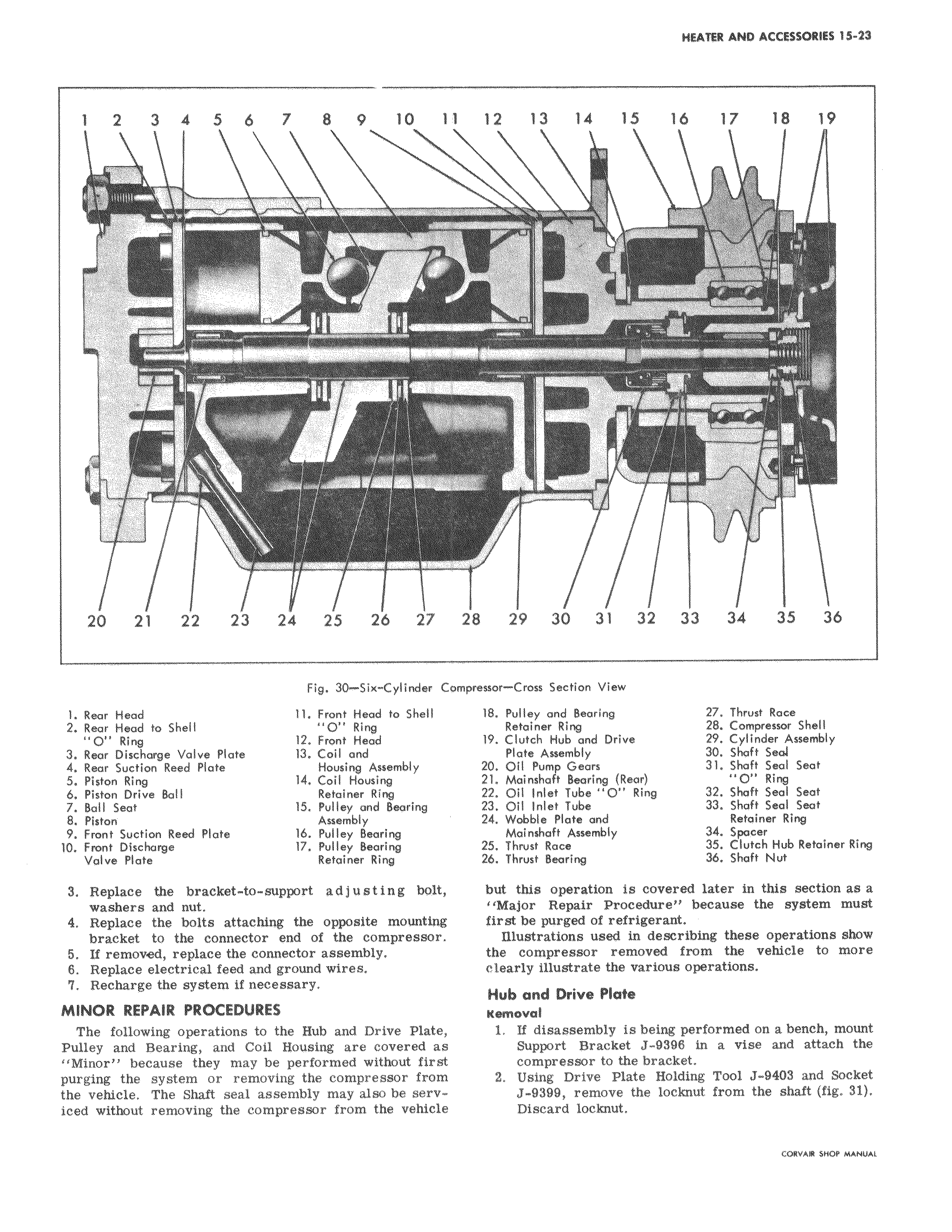
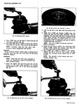
1 2 3 4 5 6 7 8 9 l4 1 c 5 qnnnl wn All I 111 i l h 20 21 22 23 24 25 26 27 Fig 30 Six Cylinder C 1 Rear Hood 11 Front Head to Shelf 2 Rear Mead to Shelf O Ring 0 1 Ring 12 Front Head 3 Rear Discharge Valve Plate 13 Coil and 4 Roar Suction Reed Plate Housing Assembly 5 Piston Ring 14 Coil Housing 6 Piston Drive Ball Retainer Ring 7 Ball Seat 15 Pulley and Bearing 8 Piston Assembly 9 Front Suction Reed Plate lb Pulley Bearing 10 Front Discharge 17 Pulley Bearing Volvo Plate Retainer Ring 3 Replace the bracket to support adjusting bolt washers and nut 4 Replace the bolts attaching the opposite mounting bracket to the connector end of the compressor 5 If removed replace the connector assembly 6 Replace electrical feed and ground wires 7 Recharge the system if necessary MINOR REPAIR PROCEDURES The following operations to the Hub and Drive Plate Pulley and Bearing and Coil Housing are covered as Minor because they may be performed without first purging the system or removing the compressor from the vehicle The Shaft seal assembly may also be serviced without removing the compressor from the vehicle 1 12 13 14 15 16 17 18 19 i a 1 F444 r 28 29 30 31 32 33 34 35 36 mpreasor Cross Section View 18 Pulley and Bearing 27 Thrust Race Retainer Ring 28 Compressor Shell 19 Clutch Hub and Drive 29 Cylinder Assembly Plate Assembly 30 Shaft seal Z0 Oil Pump Gears 31 Shaft Seal Seat 21 Mainshaft Bearing Rear O Ring 22 Oil Inlet Tube O Ring 32 Shaft Seal Seat 23 Oil Inlet Tube 33 Shaft Seal Seat 24 Wobble Plate and Retainer Ring Mainshaft Assembly 34 Spacer 25 Thrust Race 35 Clutch Hub Retainer Ring 26 Thrust Bearing 36 Shaft Nut but this operation is covered later in this section as a Major Repair Procedure because the system must first be purged of refrigerant Illustrations used in describing these operations show the compressor removed from the vehicle to more clearly illustrate the various operations Hub and Driv Plate Kamoval 1 If disassembly is being performed on a bench mount Support Bracket J 9998 in a vise and attach the compressor to the bracket 2 Using Drive Plate Holding Tool J 9403 and Socket J 9399 remove the locknut from the shaft fig 31 Discard locknut CORVAR SHOP MANUAL