Jeep Parts Wiki | Ford Parts Wiki
Home | Search | Browse
|
Corvair Chassis Shop Manual December 1964 |
|
Prev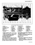
 Next
Next
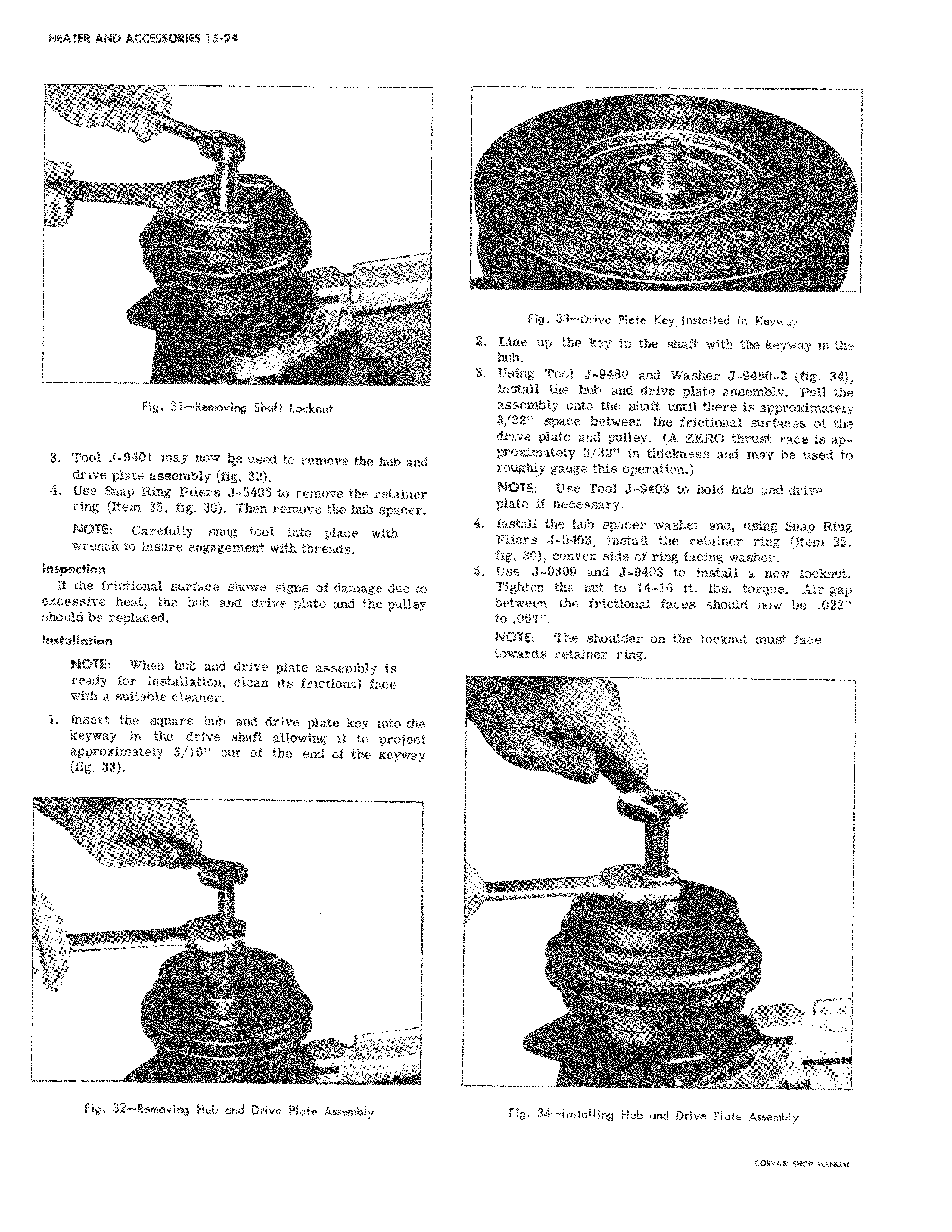
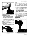
Fig 31 Removing Shaft Locknut 3 Tool J 9401 may now Ile used to remove the hub drive plate assembly fig 32 Ring 0r remove the retainer Item 0v remove m hub m NOTE Carefully snug tool into place with insure engagement threads Inspection v w s signs of damage due to excessive heat the hub and drive plate and the pulley should be replaced Installation h and plate assembly ready for installation clean its frictional face 1 a suitable cleaner Insert square 1 hub and into 1 e drive shaft allowing it to projec approximately I the end the 57 11 Fig 32 Removing Hub and Drive Plate Assembly I Fig 33 Drive plate Key Installed in Keyway 2 Linle up the key in the shaft with the keyway in the hubL 3 Usitig Tool J 9480 and Washer J 9480 2 fig 34 install the hub and drive plate assembly Pull the assembly onto the shaft until there is approximately 3 3p space betweeL the frictional surfaces of the driie plate and pulley A ZERO thrust race is approXimately 3 32 in thickness and may be used to roughly gauge this operation NOTE Use Tool J 9403 to hold hub and drive ploe if necessary 4 Insi ail the hub spacer washer and using Snap Ring Pliers J 5403 install the retainer ring Item 35 fig 130 convex side of ring facing washer 5 Use J 9399 and J 9403 to install a new loclmut Tighten the nut to 14 i6 ft lbs torque Air gap between the frictional faces should now be 022 to 057 NOTE The shoulder on the locknut must face towards retainer ring 1 1 77 Fig 34 Installing Hub and Drive Plate Assembly