Jeep Parts Wiki | Ford Parts Wiki
Home | Search | Browse
|
Corvair Chassis Shop Manual December 1964 |
|
Prev
 Next
Next
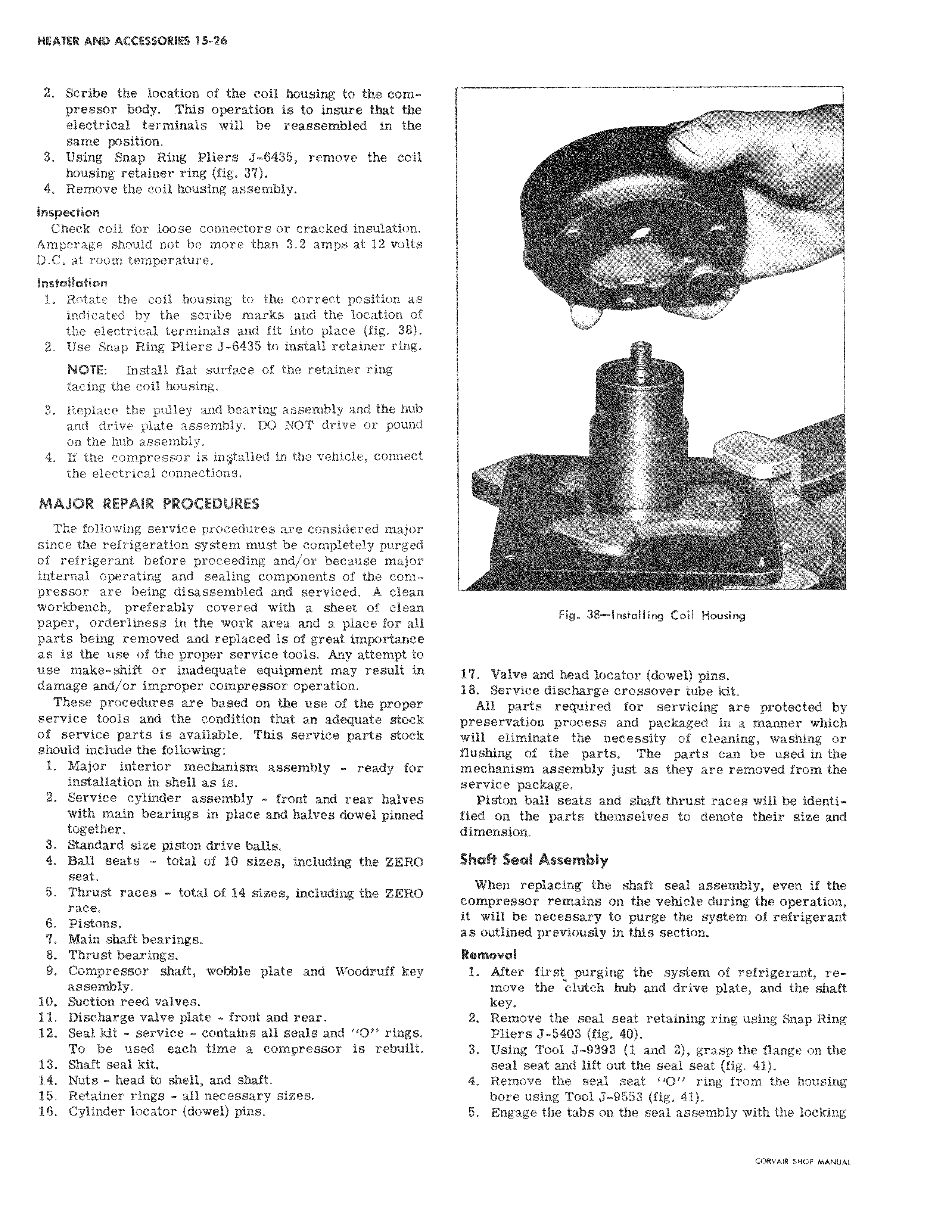
2 Scribe the location of the coil housing to the compressor body This operation is to insure that the electrical terminals will be reassembled in thel same position 3 Using Snap Ring Pliers J 6435 remove the coil housing retainer ring fig 37 4 Remove the coil housing assembly Inspection Check coil for loose connectors or cracked insulation Amperage should not be more than 3 2 amps at 12 volts D C at room temperature Installation 1 Rotate the coil housing to the correct position a indicated by the scribe marks and the location of the electrical terminals and fit into place fig 38 2 Use Snap Ring Pliers J 6435 to install retainer ring NOTE Install flat surface of the retainer ring facing the coil housing 3 Replace the pulley and bearing assembly and the hu and drive plate assembly DO NOT drive or poun on the hub assembly 4 If the compressor is in Stalled in the vehicle connect the electrical connections MAJOR REPAIR PROCEDURES ii The following service procedures are considered majo since the refrigeration system must be completely purgei of refrigerant before proceeding and or because major internal operating and sealing components of the compressor are being disassembled and serviced A clean workbench preferably covered with a sheet of clean paper orderliness in the work area and a place for al parts being removed and replaced is of great importanc as is the use of the proper service tools Any attempt t use make shift or inadequate equipment may result damage and or improper compressor operation i These procedures are based on the use of the proper service tools and the condition that an adequate stock of service parts is available This service parts stock should include the following 1 Major interior mechanism assembly ready fo installation in shell as is 2 Service cylinder assembly front and rear halve with main bearings in place and halves dowel pinned together 3 Standard size piston drive balls 4 Ball seats total of 10 sizes including the ZERO seat 5 Thrust races total of 14 sizes including the ZER race 6 Pistons i 7 Main shaft bearings 8 Thrust bearings 9 Compressor shaft wobble plate and VVoodruff key assembly 10 Suction reed valves I 11 Discharge valve plate front and rear 12 Seal kit service contains all seals and 11011 rings To be used each time a compressor is rebuilt 13 Shaft seal kit i 14 Nuts head to shell and shaft 15 Retainer rings all necessary sizes 16 Cylinder locator dowel pins i z i v 4 e Fig 38 Installing Coil Housing 17 Valve and head locator dowel pins 18 Service discharge crossover tube kit All parts required for servicing are protected by preservation process and packaged in a manner which will eliminate the necessity of cleaning washing or flushing of the parts The parts can be used in the mechanism assembly just as they are removed from the service package Piston ball seats and shaft thrust races will be identified on the parts themselves to denote their size and dimension Shaft Seal Assembly When replacing the shaft seal assembly even if the compressor remains on the vehicle during the operation it will be necessary to purge the system of refrigerant as outlined previously in this section Removaf 1 Aft first purging the system of refrigerant remove the clutch hub and drive plate and the shaft key a 2 Reove the seal seat retaining ring using Snap Ring Plie s J 5403 fig 40 3 Usi g Tool J 9393 1 and 2 grasp the flange on the seal seat and lift out the seal seat fig 41 4 Remove the seal seat 1 O ring from the housing bore using Tool J 9553 fig 41 5 EngAge the tabs on the seal assembly with the locking rroven curo uA uu