Jeep Parts Wiki | Ford Parts Wiki
Home | Search | Browse
|
Corvair Chassis Shop Manual December 1964 |
|
Prev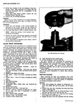
 Next
Next
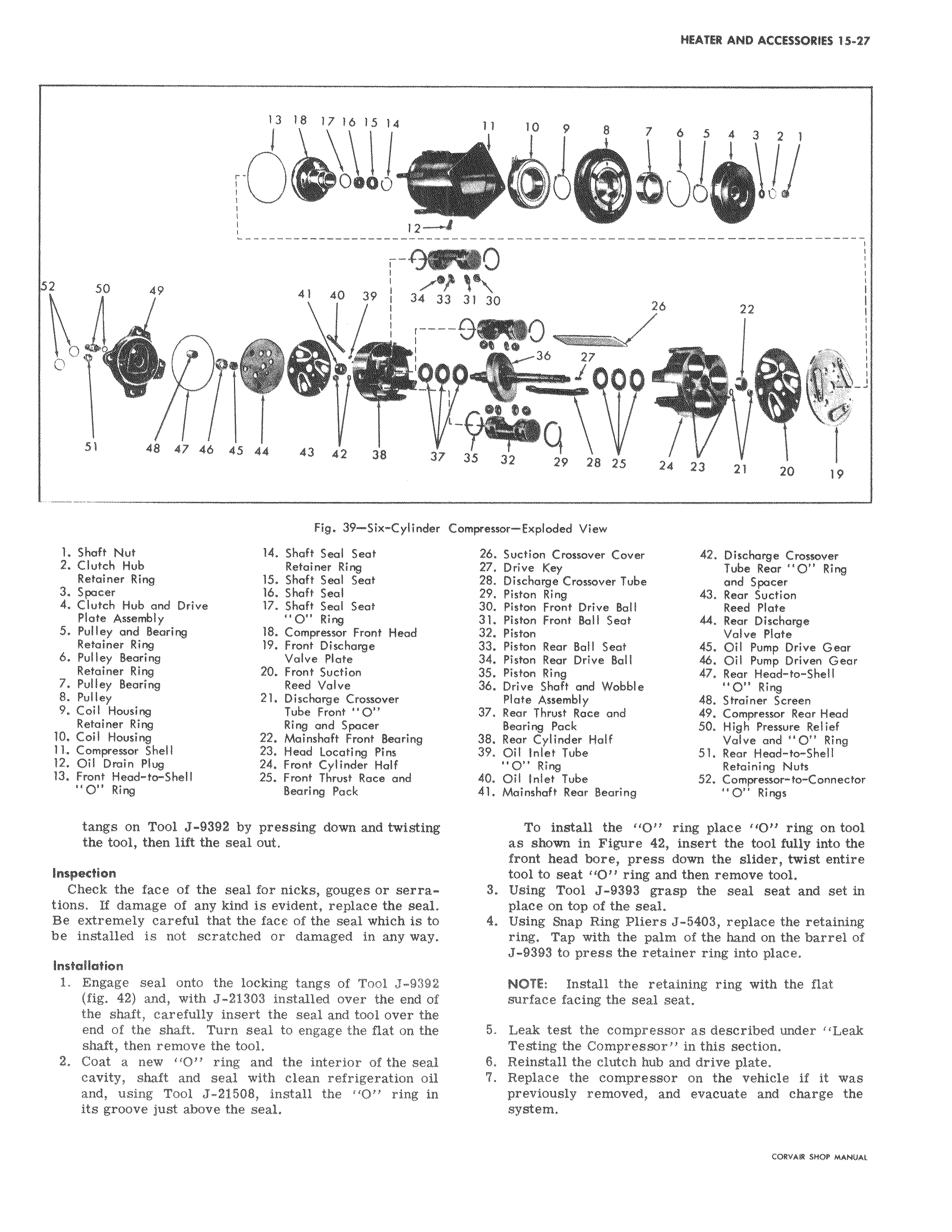
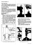
13 18 17 16 15 14 j l I I J I 12 1 F 4 W 50 49 41 40 39 j 34 33 T i 1 O n 1 0 P91 To 14 7 1 W 51 48 47 46 45 44 43 42 38 37 Fig 39 Six Cylinder C 1 Shaft Nut 14 Shaft Seal Seat 2 Clutch Hub Retainer Ring Retainer Ring 15 Shaft Seal Seat 3 Spacer 16 Shaft Seal 4 Clutch Hub and Drive 17 Shaft Seal Seat Plate Assembly O Ring 5 Pulley and Bearing 18 Compressor Front Head Retainer Ring 19 Front Discharge 6 Pulley Bearing Valve Plate Retainer Ring 20 Front Suction 7 Pulley Bearing Reed Valve 8 Pulley 21 Discharge Crossover 9 Coil Housing Tube Front O Retainer Ring Ring and Spacer 10 Coil Housing 22 Moinshaft Front Bearing I1 Compressor Shell 23 Head Locating Pins 12 Oil Drain Plug 24 Front Cylinder Half 13 Front Head to Shell 25 Front Thrust Race and O Ring Bearing Pack tangs on Tool J 9392 by pressing down and twisting the tool then lift the seal out Inspection Check the face of the seal for nicks gouges or serrations If damage of any kind is evident replace the seal Be extremely careful that the face of the seal which is to be installed is not scratched or damaged in any way Installation 1 Engage seal onto the locking tangs of Tool J 9392 fig 42 and with J 21303 installed over the end of the shaft carefully insert the seal and tool over the end of the shaft Turn seal to engage the flat on the shaft then remove the tool 2 Coat a new O ring and the interior of the seal cavity shaft and seal with clean refrigeration oil and using Tool J 21508 install the O ring in its groove just above the seal 11 10 9 8 7 b 5 4 3 2 1 C i i i 31 30 26 22 I v v v 27 000 35 32 29 28 25 24 23 21 20 19 ompressor Exploded View 26 Suction Crossover Cover 42 Discharge Crossover 27 Drive Key Tube Rear 0 Ring 28 Discharge Crossover Tube and Spacer 29 Piston Ring 43 Rear Suction 30 Piston Front Drive Boll Reed Plate 31 Piston Front Boll Seat 44 Rear Discharge 32 Piston Valve Plate 33 Piston Rear Boll Sect 45 Oil Pump Drive Gear 34 Piston Rear Drive Boll 46 Oil Pump Driven Gear 35 Piston Ring 47 Rear Head to Shell 36 Drive Shaft and Wobble O Ring Plate Assembly 48 Strainer Screen 37 Rear Thrust Race and 49 Compressor Rear Head Bearing Pack 50 High Pressure Relief 38 Rear Cylinder Half Valve and O Ring 39 Oil Inlet Tube 51 Rear Head to Shell O Ring Retaining Nuts 40 Oil Inlet Tube 52 Compressor to Connector 41 Moinshaft Rear Bearing CY Rings To install the O ring place 1O ring on tool as shown in Figure 42 insert the tool fully into the front head bore press down the slider twist entire tool to seat O ring and then remove tool 3 Using Tool J 9393 grasp the seal seat and set in place on top of the seal 4 Using Snap Ring Pliers J 5403 replace the retaining ring Tap with the palm of the hand on the barrel of J 9393 to press the retainer ring into place NOTE Install the retaining ring with the flat surface facing the seal seat 5 Leak test the compressor as described under Leak Testing the Compressor in this section 6 Reinstall the clutch hub and drive plate 7 Replace the compressor on the vehicle if it was previously removed and evacuate and charge the system CORVAIR SHOP MANUAL