Jeep Parts Wiki | Ford Parts Wiki
Home | Search | Browse
|
Corvair Chassis Shop Manual December 1964 |
|
Prev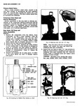
 Next
Next
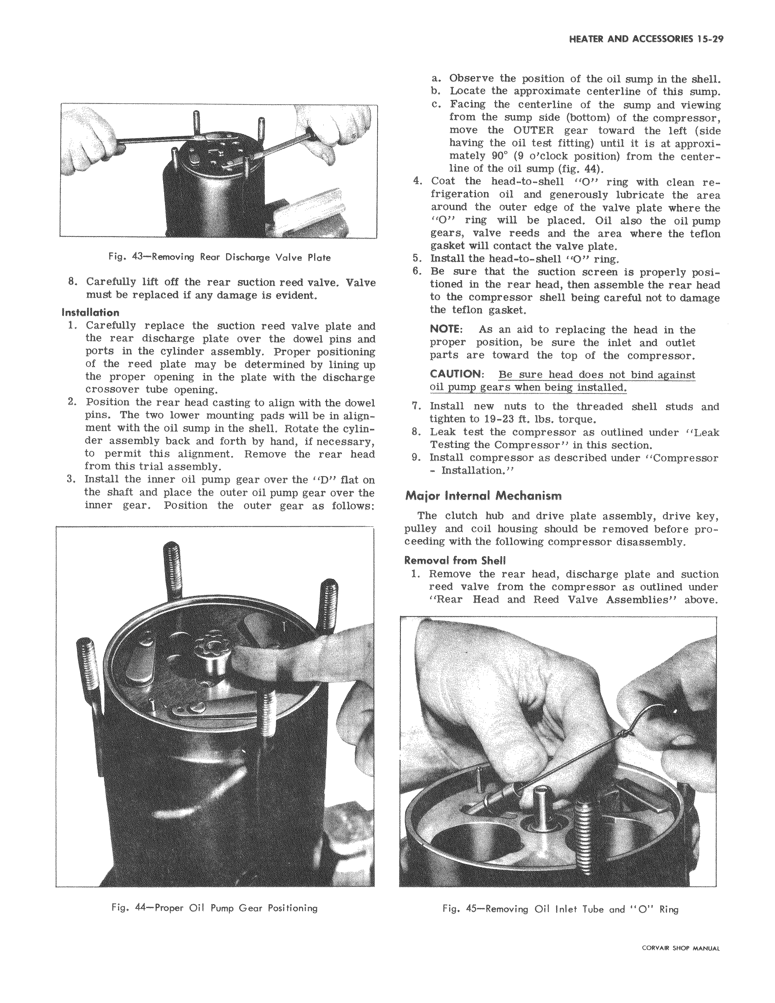
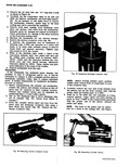
Fig 43 Removing Rear Discharge Valve Plate 8 Carefully lift off the rear suction reed valve Valv must be replaced if any damage is evident Installation 1 Carefully replace the suction reed valve plate an the rear discharge plate over the dowel pins an ports in the cylinder assembly Proper positionin of the reed plate may be determined by lining u the proper opening in the plate with the discharg crossover tube opening 2 Position the rear head casting to align with the dowe pins The two lower mounting pads will be in align ment with the oil sump in the shell Rotate the cylin der assembly back and forth by hand if necessary to permit this alignment Remove the rear hea from this trial assembly 3 Install the inner oil pump gear over the I D flat o the shaft and place the outer oil pump gear over th inner gear Position the outer gear as foilowe Fig 44 Proper Oil Pump Gear Positioning a Observe the position of the oil sump in the shell b Locate the approximate centerline of this sump c Facing the centerline of the sump and viewing from the sump side bottom of the compressor move the OUTER gear toward the left side having the oil test fitting until it is at approximately 90 9 o clock position from the centerline of the oil sump fig 44 4 Coat the head to shell O ring with clean refrigeration oil and generously lubricate the area around the outer edge of the valve plate where the O ring will be placed Oil also the oil pump gears valve reeds and the area where the teflon gasket will contact the valve plate 5 Install the head to shell 1O ring 6 Be sure that the suction screen i8 properly posie tioned in the rear head then assemble the rear head to the compressor shell being careful not to damage the teflon gasket i NOTE As an aid to replacing the head in the proper position be sure the inlet and outlet parts are toward the top of the compressor CAUTION Be sure head does not bind against e oil pump gears when being installed 1 7 Install new nuts to the threaded shell studs and tighten to 19 23 ft lbs torque 8 Leak test the compressor as outlined under Leak Testing the Compressor in this section 9 Install compressor as described under Compressor Installation n e Major Internal Mechanism The clutch hub and drive plate assembly drive key pulley and coil housing should be removed before proceeding with the following compressor disassembly Removal from Shell 1 Remove the rear head discharge plate and suction reed valve from the compressor as outlined under Rear Head and Reed Valve Assemblies above i Fig 45 Removing Oil Inlet Tube and O Ring