Jeep Parts Wiki | Ford Parts Wiki
Home | Search | Browse
|
Corvair Chassis Shop Manual December 1964 |
|
Prev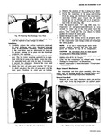
 Next
Next
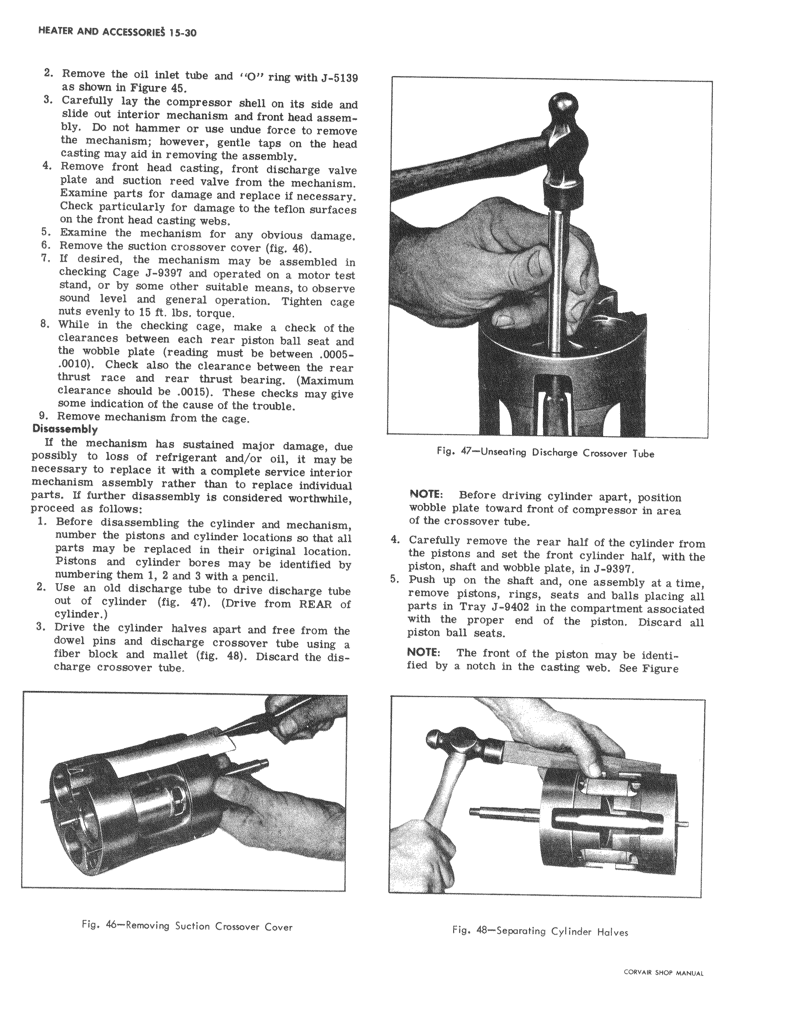
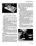
2 Remove the oil inlet tube and O ring with J 5131 as shown in Figure 45 3 Carefully lay the compressor shell on its side and slide out interior mechanism and front head assembly Do not hammer or use undue force to remove the mechanism however gentle taps on the head casting may aid in removing the assembly I 4 Remove front head casting front discharge valv e plate and suction reed valve from the mechani s Examine parts for damage and replace if necessary Check particularly for damage to the teflon surfaces on the front head casting webs 5 Examine the mechanism for any obvious damage 6 Remove the suction crossover cover fig 48 7 If desired the mechanism may be assembled checking Cage J 9397 and operated on a motor te stand or by some other suitable means to observe sound level and general operation Tighten cage nuts evenly to 15 ft lbs torque 8 While in the checking cage make a check of the clearances between each rear piston ball seat az the wobble plate reading must be between 0005 0010 Check also the clearance between the realh thrust race and rear thrust bearing Maximum clearance shauld be 0015 These checks may give some indication of the cause of the trouble 9 Remove mechanism from the cage Disassembly If the mechanism has sustained major damage d possibly to loss of refrigerant and or oil it may necessary to replace it with a complete service interior mechanism assembly rather than to replace individual parts If further disassembly is considered worthwhile proceed as follows 1 Before disassembling the cylinder and mecbanism number the pistons and cylinder locations so that all parts may be replaced in their original location l Pistons and cylinder bores may be identified by numbering them 1 2 and 3 with a pencil 2 Use an old discharge tube to drive discharge tube out of cylinder fig 47 Drive from REAR of cylinder 3 Drive the cylinder halves apart and free from the dowel pins and discharge crossover tube using a fiber block and mallet fig 48 Discard the discharge crossover tube Fig 46 Removing Suction Crossover Cover Fig 47 Unseating Diachorge Crossover Tube NOTE Before driving cylinder apart position wobble plate toward front of compressor in area of the crossover tube 4 Carefully remove the rear half of the cylinder from the pistons and set the front cylinder half with the piston shaft and wobble plate in J 9397 5 Push up on the shaft and one assembly at a time remove pistons rings seats and bails placing all parts in Tray J 9402 in the compartment associated with the proper end of the piston Discard all piston ball seats NOTE The front of the piston may be identified by a notch in the casting web See Figure Fig 48 Separating Cylinder Halves