Jeep Parts Wiki | Ford Parts Wiki
Home | Search | Browse
Prev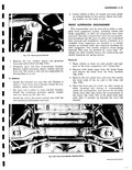
 Next
Next
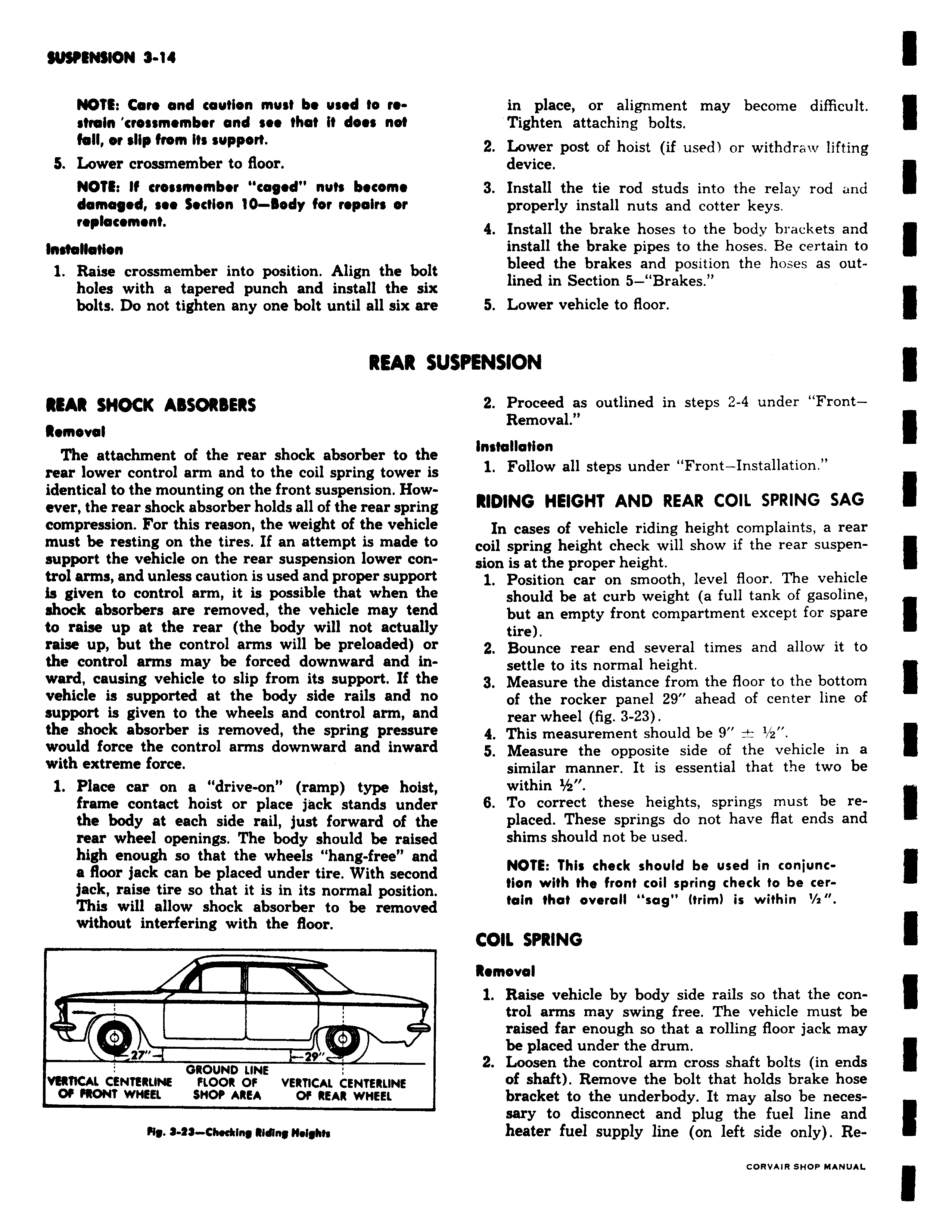
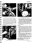
NOTE Care and caution must be used to restrain crossmombor and see that it does not fall or slip from its support S Lower crossmember to floor NOTE If eros mombor cogod nuts become damaged see Section 10 Body for repairs or replacement Installation 1 Raise crossmember into position Align the bolt holes with a tapered punch and install the six bolts Do not tighten any one bolt until all six are REAR su REAR SHOCK ABSORBERS Removal The attachment of the rear shock absorber to the rear lower control arm and to the coil spring tower is identical to the mounting on the front suspension However the rear shock absorber holds all of the rear spring compression For this reason the weight of the vehicle must be resting on the tires If an attempt is made to support the vehicle on the rear suspension lower control arms and unless caution is used and proper support is given to control arm it is possible that when the shock absorbers are removed the vehicle may tend to raise up at the rear the body will not actually raise up but the control arms will be preloaded or the control arms may be forced downward and inward causing vehicle to slip from its support If the vehicle is supported at the body side rails and no support is given to the wheels and control arm and the shock absorber is removed the spring pressure would force the control arms downward and inward with extreme force 1 Place car on a drive on ramp type hoist frame contact hoist or place jack stands under the body at each side rail just forward of the rear wheel openings The body should be raised high enough so that the wheels hang free and a floor jack can be placed under tire With second jack raise tire so that it is in its normal position This will allow shock absorber to be removed without interfering with the floor 2r 29 GROUND LINE VERTICAL CENTERIINE FLOOR Of VERTICAL CENTERLINE Of FRONT WHEEL SHOP AREA Of REAR WHEEL My l 23 CMeAinq Ridleq 11 fqAh in place or alignment may become difficult Tighten attaching bolts 2 Lower post of hoist if used or withdraw lifting device 3 Install the tie rod studs into the relay rod and properly install nuts and cotter keys 4 Install the brake hoses to the body brackets and install the brake pipes to the hoses Be certain to bleed the brakes and position the hoses as outlined in Section 5 Brakes 5 Lower vehicle to floor iPENSION 2 Proceed as outlined in steps 2 4 under FrontRemoval Installation 1 Follow all steps under Front Installation RIDING HEIGHT AND REAR COIL SPRING SAG In cases of vehicle riding height complaints a rear coil spring height check will show if the rear suspension is at the proper height 1 Position car on smooth level floor The vehicle should be at curb weight a full tank of gasoline but an empty front compartment except for spare tire 2 Bounce rear end several times and allow it to settle to its normal height 3 Measure the distance from the floor to the bottom of the rocker panel 29 ahead of center line of rear wheel fig 3 23 4 This measurement should be 9 i z 5 Measure the opposite side of the vehicle in a similar manner It is essential that the two be within 1 z 6 To correct these heights springs must be replaced These springs do not have flat ends and shims should not be used NOTE This check should be used in conjunction with the front coil spring check to be certain that overall sag trim is within 1 2 COIL SPRING Removal 1 Raise vehicle by body side rails so that the control arms may swing free The vehicle must be raised far enough so that a rolling floor jack may be placed under the drum 2 Loosen the control arm cross shaft bolts in ends of shaft Remove the bolt that holds brake hose bracket to the underbody It may also be neces sary to disconnect and plug the fuel line and heater fuel supply line on left side only Re