Jeep Parts Wiki | Ford Parts Wiki
Home | Search | Browse
Prev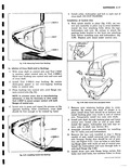
 Next
Next
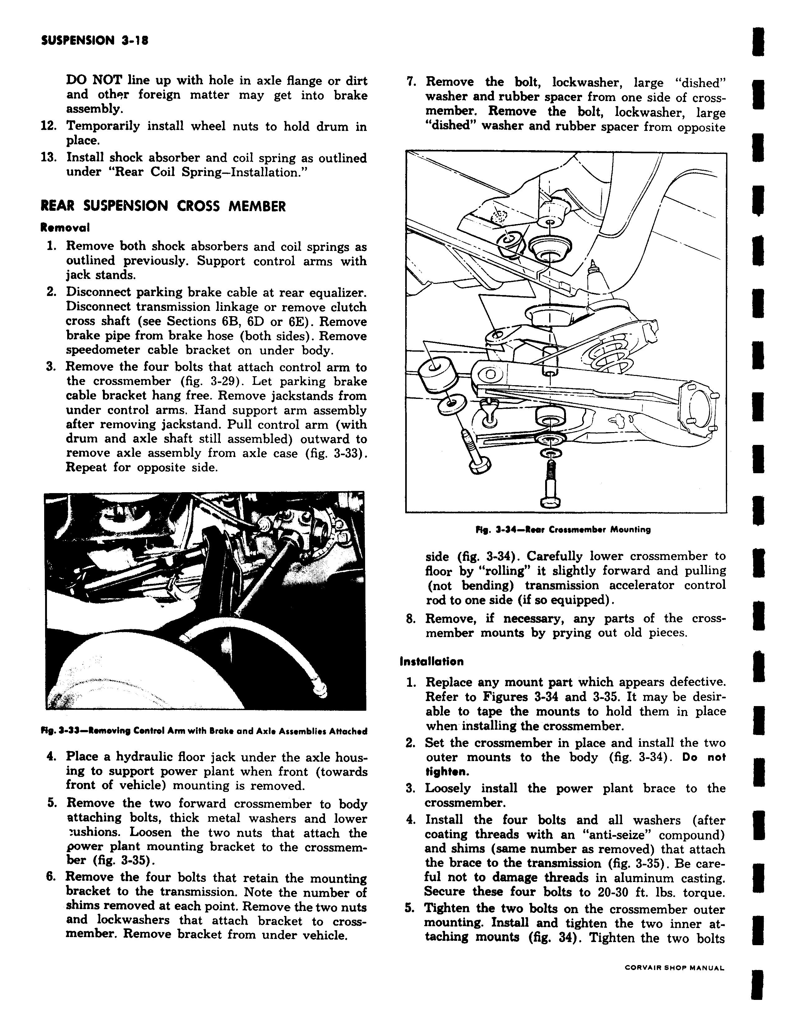
DO NOT line up with hole in axle flange or dirt and othPr foreign matter may get into brake assembly 12 Temporarily install wheel nuts to hold drum in place 13 Install shock absorber and coil spring as outlined under Rear Coil Spring Installation REAR SUSPENSION CROSS MEMBER Removal 1 Remove both shock absorbers and coil springs as outlined previously Support control arms with jack stands 2 Disconnect parking brake cable at rear equalizer Disconnect transmission linkage or remove clutch cross shaft see Sections 6B 6D or 6E Remove brake pipe from brake hose both sides Remove speedometer cable bracket on under body 3 Remove the four bolts that attach control arm to the crossmember fig 3 29 Let parking brake cable bracket hang free Remove jackstands from under control arms Hand support arm assembly after removing jackstand Pull control arm with drum and axle shaft still assembled outward to remove axle assembly from axle case fig 3 33 Repeat for opposite side 3 rr RR 9 33 Removing Control Arm with Brake and Axle Assemblies Attached 4 Place a hydraulic floor jack under the axle housing to support power plant when front towards front of vehicle mounting is removed 5 Remove the two forward crossmember to body attaching bolts thick metal washers and lower ushions Loosen the two nuts that attach the power plant mounting bracket to the crossmember fig 3 35 6 Remove the four bolts that retain the mounting bracket to the transmission Note the number of shims removed at each point Remove the two nuts and lockwashers that attach bracket to crossmember Remove bracket from under vehicle 7 Remove the bolt lockwasher large dished washer and rubber spacer from one side of crossmember Remove the bolt lockwasher large dished washer and rubber spacer from opposite Y CD y er Jl Fly 3 34 Rwr Crossmember Mounting side fig 3 34 Carefully lower crossmember to floor by rolling it slightly forward and pulling not bending transmission accelerator control rod to one side if so equipped 8 Remove if necessary any parts of the crossmember mounts by prying out old pieces Installation 1 Replace any mount part which appears defective Refer to Figures 3 34 and 3 35 It may be desirable to tape the mounts to hold them in place when installing the crossmember 2 Set the crossmember in place and install the two outer mounts to the body fig 3 34 Do not tighten 3 Loosely install the power plant brace to the crossmember 4 Install the four bolts and all washers after coating threads with an anti seize compound and shims same number as removed that attach the brace to the transmission fig 3 35 Be careful not to damage threads in aluminum casting Secure these four bolts to 20 30 ft lbs torque 5 Tighten the two bolts on the crossmember outer mounting Install and tighten the two inner attaching mounts fig 34 Tighten the two bolts