Jeep Parts Wiki | Ford Parts Wiki
Home | Search | Browse
|
Corvette Assembly Manual January 1978 |
|
Prev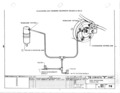
 Next
Next
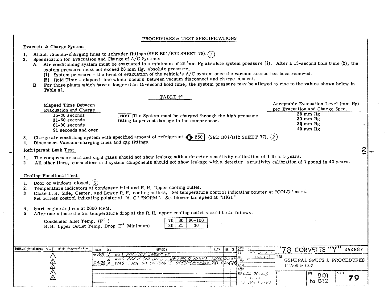
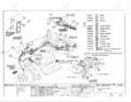
PROCEDURES TEST SPECIFICATIONS Evacuate Charge gystem l Attach vacuum charg lng lines to schrader fittings SEE B0l B12 SHEET lB 2 Specification lor Evacuation and Charge of A C Systems A Air conditioning system must be evacuated to a minimum of 25 mm I lg absolute system pressure 1 After a 15 second hold time 2 the system pressure must not exceed 28 mm l lg absolute pressure 1 System pressure the level ot evacuation of the vehicle s A C system once the vacuum source has been removed 2 Hold Time elapsed time which occurs between vacuum disconnect and charge connect B Fogltligige plants which have a longer than 15 second hold time the system pressure may he allowed to rise to the values shown below in Ta e TABLE 1 Elapsed Time Between Acceptable Evacuation Level mm Hg Evacuation and Charge pier Evacuation and Charge Spec 15 30 i The System must be charged through me high pressure 28 mm H8 g i itt1ng to prevent damage to Uie compressor mm gg on mrn g 91 seconds and over 40 mm Hg 3 Charge air conditiong system with specitled amount oi refrigerant gm SEE BM B12 SHEET 77 4 Disconnect Vacuum charging lines and cap fittings Refrigerant Leak Test E l The compressor seal and sight glass should not show leakage with a detector sensitivity calibration oi l lb in 5 years F 2 All other lines connections and system components should not show leakage with a detector sensitivity calibration of l pound in 40 years Cooling Functional Test l Door or windows closed Q 2 Temperature indicators at condenser inlet and R H Upper cooling outlet 3 Close L ll Side Center and Lower R H cooling outlets Set temperature control indicating pointer at COLD mark Set outlets control indicating pointer at A C NORM set blower tan speed at l llGl l 4 Surt engine and run at 2000 RPM 5 After one minute the air temperature drop at the R H upper cooling outlet should be as follows Condenser Inlet Temp 1 num 90 100 a i 1 upper Outlet Temp Drop r Minimum EQE 30 nvunaiw l uane a t m wl mmm wm K EE i In 1 Vu 4 AX 0 d 1 was 5 5 Queer pr E g HI 8 COR FTE i 6 B8 g uree Z iii ea TrJ ee m L Ze 22 ra f s A SMS s F mS jg i F l Ann ie Cart g g gg 5 te Bm i lrtr 4 rv i 1 M to mz 79 ee ee M V ee