Jeep Parts Wiki | Ford Parts Wiki
Home | Search | Browse | Marketplace | Messages | FAQ | Guest
Prev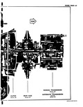

 Next
Next
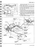
SERVICE 0 INTRO In order to service components of the Corvair power train efficiently the serviceman must familiarize himself with the location and accessibility of the engine axle and transmission components Many service operations may be performed on the vehicle without disturbing the power train unit In other cases however it will be necessary to remove the entire power train from the vehicle to perform the necessary servicing Toward this end the power train has been designed for package removal from the vehicle To the serviceman inexperienced with the Corvair power train the exact approach to a particular service problem will not always be obvious For this reason adequate introductory information including a Service Reference Guide has been included in the more complex power train component sections to assist the serviceman in determining the best approach for his particular service problem Before beginning any service operation the serviceman should consult this material until he has become thoroughly familiar with the best approaches for all service operations In general the primary question to be answered is Will it be necessary to remove the power train to do the job The Service Reference Guide will answer this question as well as offer other valuable service information The importance of using proper equipment and following recommended procedures when removing and installing the power train cannot be over emphasized This is extremely important from the standpoint of both safety to the serviceman and prevention of damage to the power train components The preferred method of removal and installation described in this manual utilizes Power Train Fixture J 7894 mounted to a suitable hydraulic jack such as J 8394 with the vehicle on a hoist Equipment limitaREMOVAL OF 1 On coupe and sedan models remove spare tire on station wagon models remove engine access cover 2 Remove carburetor air cleaners 3 Disconnect return air hose for air heater if car is so equipped 4 Remove engine to body front seal retainer 5 Disconnect return spring and throttle rod from left carburetor at the carburetor cross shaft 6 Disconnect tunnel choke cable fig 6 2 at its attachment to the choke bridle by loosening the screws securing the cable sheath clamp and cable clamp Inset fig 6 2 7 Make the following electrical disconnections fig 6 3 PERATIONS IUCTION tions may require a modified approach to this operation but the basic principles and precautions remain the same Listed below are some of the major precautions to be observed when removing or installing a power train Do not support the complete power train except at the engine pan rail Under no circumstances should it be supported on the pan itself Jacking Fixture J 7894 has been designed to properly support and lock the power train in a balanced position No jacking fixture or floor support should be used unless it is capable of supporting the weight of the power train approximately 460 pounds No jacking fixture of questionable stability should be used The base must be sufficiently wide and the jack adequately braced to prevent tipping or collapsing with the power train raised to the maximum lift position of the jack Rough or uneven floors will complicate this problem The center of gravity or balance point of the complete power train is located approximately 200 behind the front face of the cylinder block No jack should be used that does not permit the power train to be lowered gradually This is essential to avoid damage to components when tight clearances are encountered during removal If in doubt as to whether existing equipment can adequately and safely handle the power train consult the equipment manufacturer All service operations contained in this section pertain to the removal and installation of the complete power train as well as the separation and assembly of the engine axle transmission components Refer to Sections 6A through 6E for service information on the individual power train components POWER TRAIN a Disconnect battery cable from battery positive terminal b At generator disconnect ground strap and blue and brown leads to voltage regulator c Disconnect yellow and purple ignition leads at the starting motor harness connector in the engine compartment d Disconnect the left and right engine to body ground straps not shown e Disconnect yellow lead from ignition coil and disconnect leads to temperature and oil pressure switches 8 Raise vehicle on hoist then complete electrical disconnections by removing the battery cable and