Jeep Parts Wiki | Ford Parts Wiki
Home | Search | Browse
Prev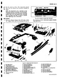

 Next
Next
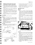
2 Adjust swivel until it enters damper door and retain with clip fig 6A 9 3 Both damper doors are adjusted the same with thermostat against the stop bracket measure from the flat of damper door edge to the exhaust duct upper edge This opening should measure approxiSERVICE C GENERAL SERVICE INFORMATION Service Operatiorus will be outlined in two parts The first part will consist of On the Vehicle service operations engine installed in vehicle while the second part will consist of Off the Vehicle service operations engine removed from vehicle The Engine Service Reference Guide is designed to show in advance the items that can be serviced on the engine while the engine is in the vehicle COMPONENT SERVICE PRO On all service operations where threads enter aluminum use anti seize compound such as Permatex No 404 or its equivalent ENGINE SHEET METAL COMPONENTS Refer to Figure 6A 11 Adequate engine cooling greatly depends on proper alignment of engine sheet metal components fig 6A 11 Handle sheet metal components carefully to prevent bending or distortion Upper Shroud Assembly Removal 1 Remove air cleaner assemblies and supports 2 Disconnect fuel lines at fuel pump and carburetors Disconnect accelerator and throttle linkage choke cable assembly and heater hose at upper shroud Remove blower belt 3 Remove carburetor cross shaft and disconnect vacuum balance tube from carburetor mounting flange and upper shroud assembly Remove both carburetors 4 Remove wire harness from each spark plug 5 Remove all fuel lines and oil level gauge 6 Remove generator bracket bolts at engine upper shroud and swivel generator bracket out of the way Remove all engine upper shroud assembly retaining screws fig 6A 12 and remove upper shroud NOTE Tip engine upper shroud assembly away from the oil filter and generator adapter mately 2 32 as shown in Figure 6A 9 View A NOTE Thermostat can be installed by attaching it to actuating rod and bracket then insert the thermostat bracket and actuating rod through the exhaust duct damper door opening 1PERATIONS Some service operations can be done either in or out of the vehicle so the most practical method should be followed depending on the conditions involved Some items like the crankshaft and camshaft involve complete engine removal from the vehicle and complete disassembly of the crankcase for their removal Component items are outlined for removal and installation under Engine Component Service Procedures and repairs are outlined under Repairs Engine Components EDURES ENGINE IN VEHICLE Installation 1 Install engine upper shroud tipping while lowering over blower assembly 4 2 4 4 2 11 t 1 t lai I7 10 a i 6 v VIEW A Fig 6A 14 Engine Upper Shroud Assembly Roar Shield and Center Shroud 1 Upper Shroud Assembly 6 Roar Shield 2 Bolt 7 Seat 3 Bolt 8 Screw 4 Screw 9 Seal Retainer S Oil Cooler Access 10 U Nufs Hole Cover