Jeep Parts Wiki | Ford Parts Wiki
Home | Search | Browse | Marketplace | Messages | FAQ | Guest
Prev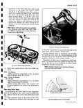

 Next
Next
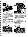
Regardless methods ir the final seat width in cylinder head should be as follows Inlet Y32 to 2 Exhaust 1 10 to Ys angle should 44 and should concentric m indicator Always dress stones to proper angle before grinding NOTE Volvo face to seat angles should be as Valves that are pitted can be refaced to the proper angle insuring correct relation between the head and valve seat shown In Figure 6A 58 Refacing Valves stem valve show excessive wear or valves that are pounded in or warped excessively should be replaced When a valve head which is pounded in or warped excessively is refacing machine Valve stems which will be ground on part or all of the valve head due to the amount of metal that must be removed to completely reface Knife edges lead to pre ignition w ke edge If the edge of the head i after grinding place the valve dress machine grinding wheel to make sure it is true and smooth 3 After setting chuck angle insert valve and grind Exhaust Valve Seat Inserts reconditioning inder head should be inspected If either valve inserts or valve guides are beyond repair cylinder head will need to he replaced as a unit a t x a MS 6A 59 1 movlng Exhaust Manifold sleeves Exhaust Manifold Sleeves Replacement NOTE Do not remove exhaust manifold sleeves unless absolutely necessary Warm cylinder head to Z00 F 1 Remove exhaust manifold sleeves with a suitable pipe wrench by turning gradually fig 6A 59 NOTE Do not tap or pry sleeves from cylinder head 2 Check exhaust manifold sleeve installation holes in cylinder head for nicks or damage 3 Coat new sleeves with anti seize compound and locate flat side parallel to exhaust push rod drain tube hole NOTE Be careful when replacing sleeves They are installed in the cylinder head with a pre At and must be started into place true with the exhaust bore in the cylinder head NOTE Sleeves are available In standard 002 and 010 oversize for service 4 Place sleeves in a container of dry ice solidified carbon dioxide for about 10 minutes 5 Warm cylinder head to about 200 F Support cylinder head to avoid damage to cooling fins NOTE Do not use an open flame 6 Remove sleeves one at a time from dry ice and tap into place with a soft tool NOTE Do not damage exhaust manifold end of sleeves they are a press fit into the exhaust manifold Cylinder Head Assembly 1 To install carburetor attaching studs if replacement is necessary coat threads with Permatex anti seize compound 404 or equivalent and install long stud e 18 24 x 418 le using Tool J 8534 2 in intake manifold flange at A on left and right bank cylinder heads fig 6A 60 to a length of 4 B 2 Install short stud a 18 18 x 24 x 2a using Tool J 8354 2 in intake manifold flange at B on left and right bank cylinder heads to a length of 16 8 3 If necessary to replace exhaust manifold studs C fig 6A 60 and 6A 61 coat new stud with anti seize compound and using Tool J 8354 3 install to a length of 8 2 NOTE Cylinder Head are identical except for location of vacuum balance tube hose connector E which Is on one side of carburetor mounting pad on the right bank and the other side on the left bank Aq 6A 60 4 Install each valve coated with SAE 30 engine oil or molykote solution in the valve guide from which it was removed or to valve guide it was fitted Lightly coat valve spring shim with petrolatum