Jeep Parts Wiki | Ford Parts Wiki
Home | Search | Browse
Prev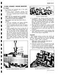
 Next
Next
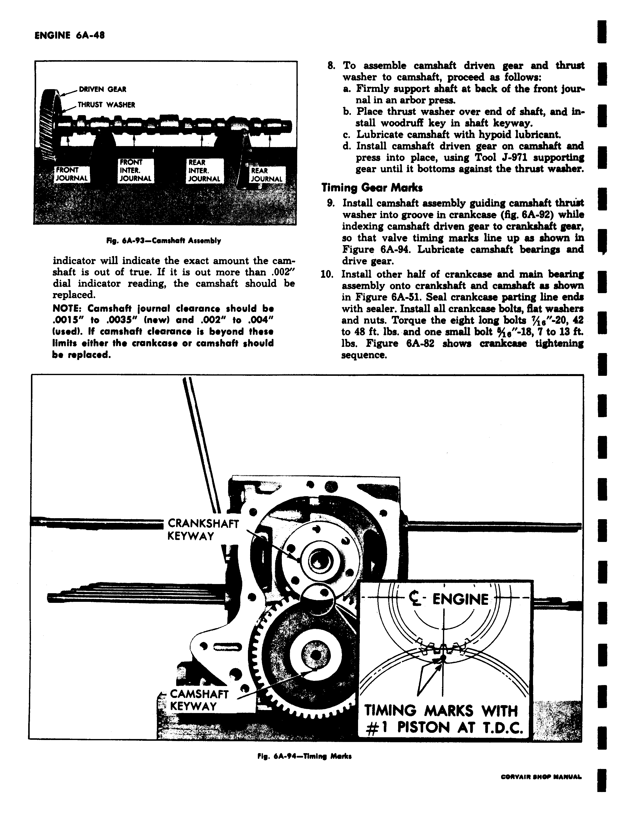
DRIVEN GEAR THRUST WASHER FR REAR FRONT INTER INTER REAR JOURNAL JOURNAL JOURNAL JOURNAL Fly 6A 93 Comshaft Assembly indicator will indicate the exact amount the camshaft is out of true If it is out more than 002 dial indicator reading the camshaft should be replaced NOTE Camshaft journal clearance should be 0015 to 0035 new and 002 to 004 used If camshaft clearance is beyond these limits either the crankcase or camshaft should be replaced CRANKSHAFT KEYWAY CAMSHAFT A KEYWAY i Fig 6A 14 8 To assemble camshaft driven gear and thrust washer to camshaft proceed as follows a Firmly support shaft at back of the front journal in an arbor press b Place thrust washer over end of shaft and install woodruff key in shaft keyway c Lubricate camshaft with hypoid lubricant d Install camshaft driven gear on camshaft and press into place using Tool J 971 supporting gear until it bottoms against the thrust washer Timing G ar Marks 9 Install camshaft assembly guiding camshaft thrust washer into groove in crankcase fig 6A 92 while indexing camshaft driven gear to crankshaft gear so that valve timing marks line up as shown in Figure 6A 94 Lubricate camshaft bearings and drive gear 10 Install other half of crankcase and main bearing assembly onto crankshaft and camshaft as shown in Figure 6A 51 Seal crankcase parting line ends with sealer Install all crankcase bolts flat washers and nuts Torque the eight long bolts 7A6 20 42 to 48 ft lbs and one small bolt e 18 7 to 13 ft lbs Figure 6A 82 shows crankcase tightening sequence ENGINE TIMING MARKS WITH 1 PISTON AT T D C Timing Marks