Jeep Parts Wiki | Ford Parts Wiki
Home | Search | Browse
Prev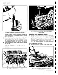
 Next
Next
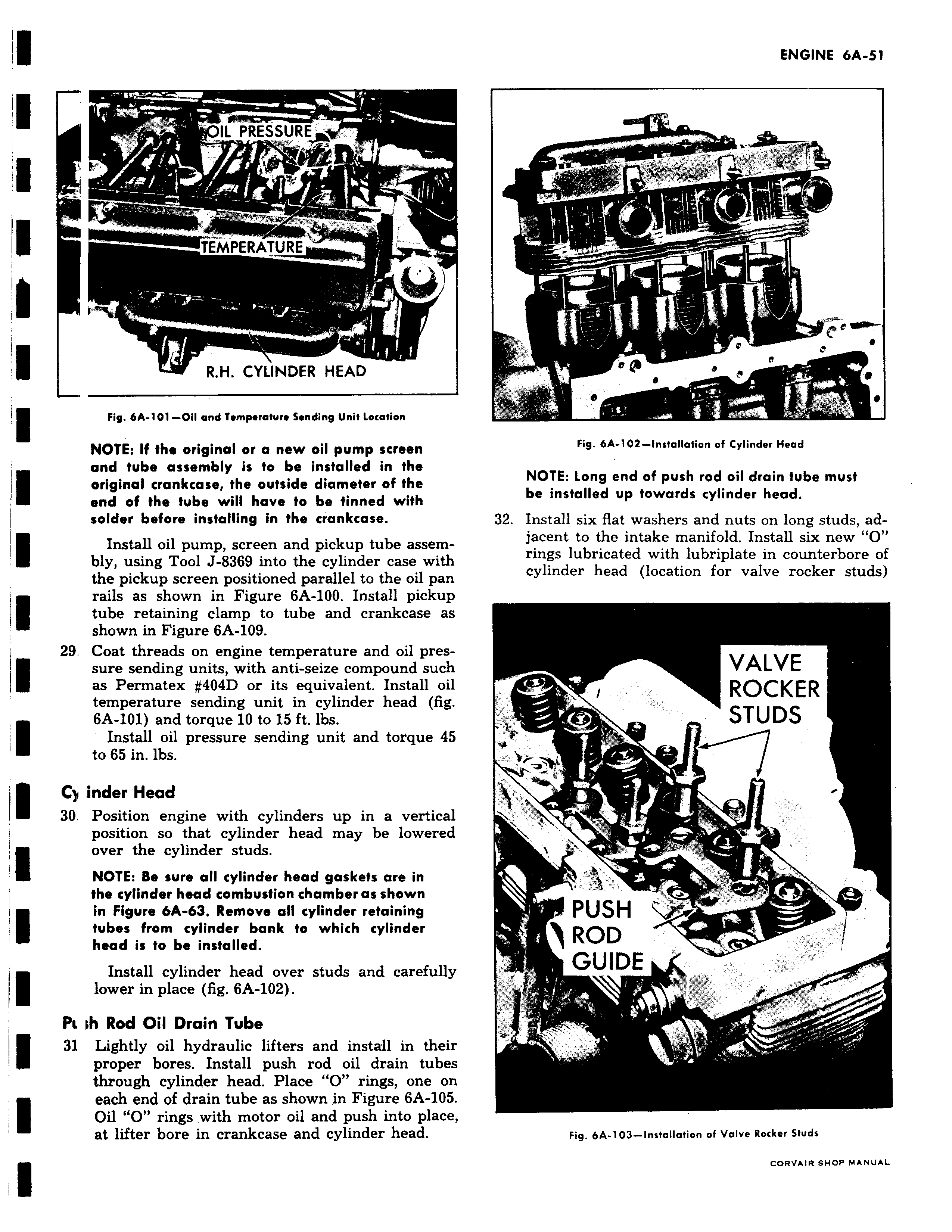
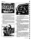
IL PREE SURE TEMPERATUR E R H CYLINDER HEADf Fig 6A 101 Oil and Trmprrafurr Sending Unit Location NOTE If the original or a new oil pump screen and tube assembly is to be installed in the original crankcase the outside diameter of the end of the tube will have to be tinned with solder before installing in the crankcase Install oil pump screen and pickup tube assembly using Tool J 8369 into the cylinder case with the pickup screen positioned parallel to the oil pan rails as shown in Figure 6A 100 Install pickup tube retaining clamp to tube and crankcase as shown in Figure 6A 109 29 Coat threads on engine temperature and oil pressure sending units with anti seize compound such as Permatex 404D or its equivalent Install oil temperature sending unit in cylinder head fig 6A 101 and torque 10 to 15 ft lbs Install oil pressure sending unit and torque 4 to 65 in lbs CIi inder Head 30 Position engine with cylinders up in a vertical position so that cylinder head may be lowered over the cylinder studs NOTE Be sure all cylinder head gaskets are in the cylinder head combustion chamber as shown in Figure bA 63 Remove all cylinder retaining tubes from cylinder bank to which cylinder head is to be installed Install cylinder head over studs and carefully lower in place fig 6A 102 PL th Rod Oil Drain Tube I 31 Lightly oil hydraulic lifters and install in then proper bores Install push rod oil drain tube through cylinder head Place O rings one or each end of drain tube as shown in Figure 6A 105 Oil O rings with motor oil and push into place at lifter bore in crankcase and cylinder head J yc r r Ilf k i r r R 4 WWI