Jeep Parts Wiki | Ford Parts Wiki
Home | Search | Browse
Prev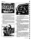
 Next
Next
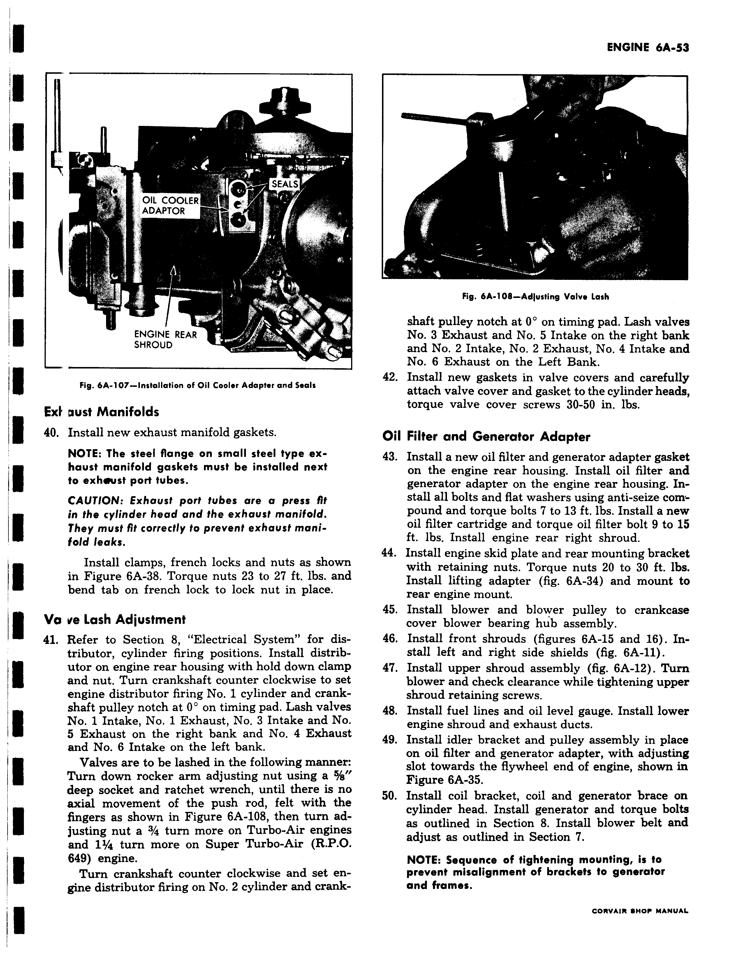
EAL OIL COOLER ADAPTOR i 4 N ENGINE REAR SHROUD Fig 6A 107 Installation of Oil Cooler Adapter and Seals ExF oust Manifolds 40 Install new exhaust manifold gaskets NOTE The steel flange on small steel type exhaust manifold gaskets must be installed next to exhwust port tubes CAUTION Exhaust port tubes are a press fit in the cylinder head and the exhaust manifold They must fit correctly to prevent exhaust manifold leaks Install clamps french locks and nuts as shown in Figure 6A 38 Torque nuts 23 to 27 ft lbs and bend tab on french lock to lock nut in place Va ve Lash Adjustment 41 Refer to Section 8 Electrical System for distributor cylinder firing positions Install distributor on engine rear housing with hold down clamp and nut Turn crankshaft counter clockwise to set engine distributor firing No 1 cylinder and crank shaft pulley notch at 0 on timing pad Lash valves No 1 Intake No 1 Exhaust No 3 Intake and No 5 Exhaust on the right bank and No 4 Exhaust and No 6 Intake on the left bank I Valves are to be lashed in the following manner Turn down rocker arm adjusting nut using a S s deep socket and ratchet wrench until there is no axial movement of the push rod felt with the fingers as shown in Figure 6A 108 then turn adjusting nut a 3 4 turn more on Turbo Air engines and 11 4 turn more on Super Turbo Air R P O 649 engine Turn crankshaft counter clockwise and set engine distributor firing on No 2 cylinder and crank S n o Fig 6A 108 Adjusting Volvo Lash shaft pulley notch at 0 on timing pad Lash valves No 3 Exhaust and No 5 Intake on the right bank and No 2 Intake No 2 Exhaust No 4 Intake and No 6 Exhaust on the Left Bank 42 Install new gaskets in valve covers and carefully attach valve cover and gasket to the cylinder heads torque valve cover screws 30 50 in lbs Oil Filter and Generator Adapter 43 Install a new oil filter and generator adapter gasket on the engine rear housing Install oil filter and generator adapter on the engine rear housing In stall all bolts and flat washers using anti seize compound and torque bolts 7 to 13 ft lbs Install a new oil filter cartridge and torque oil filter bolt 9 to 15 ft lbs Install engine rear right shroud 44 Install engine skid plate and rear mounting bracket with retaining nuts Torque nuts 20 to 30 ft lbs Install lifting adapter fig 6A 34 and mount to rear engine mount 45 Install blower and blower pulley to crankcase cover blower bearing hub assembly 46 Install front shrouds figures 6A 15 and 16 Install left and right side shields fig 6A 11 47 Install upper shroud assembly fig 6A 12 Turn blower and check clearance while tightening upper shroud retaining screws 48 Install fuel lines and oil level gauge Install lower engine shroud and exhaust ducts 49 Install idler bracket and pulley assembly in place on oil filter and generator adapter with adjusting slot towards the flywheel end of engine shown in Figure 6A 35 50 Install coil bracket coil and generator brace on cylinder head Install generator and torque bolts as outlined in Section 8 Install blower belt and adjust as outlined in Section 7 NOTE Sequence of tightening mounting is to prevent misalignment of brackets to generator and frames