Jeep Parts Wiki | Ford Parts Wiki
Home | Search | Browse
|
New Product Service Information Manual 201 January 1972 |
|
Prev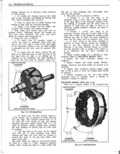
 Next
Next
1948791
1948791
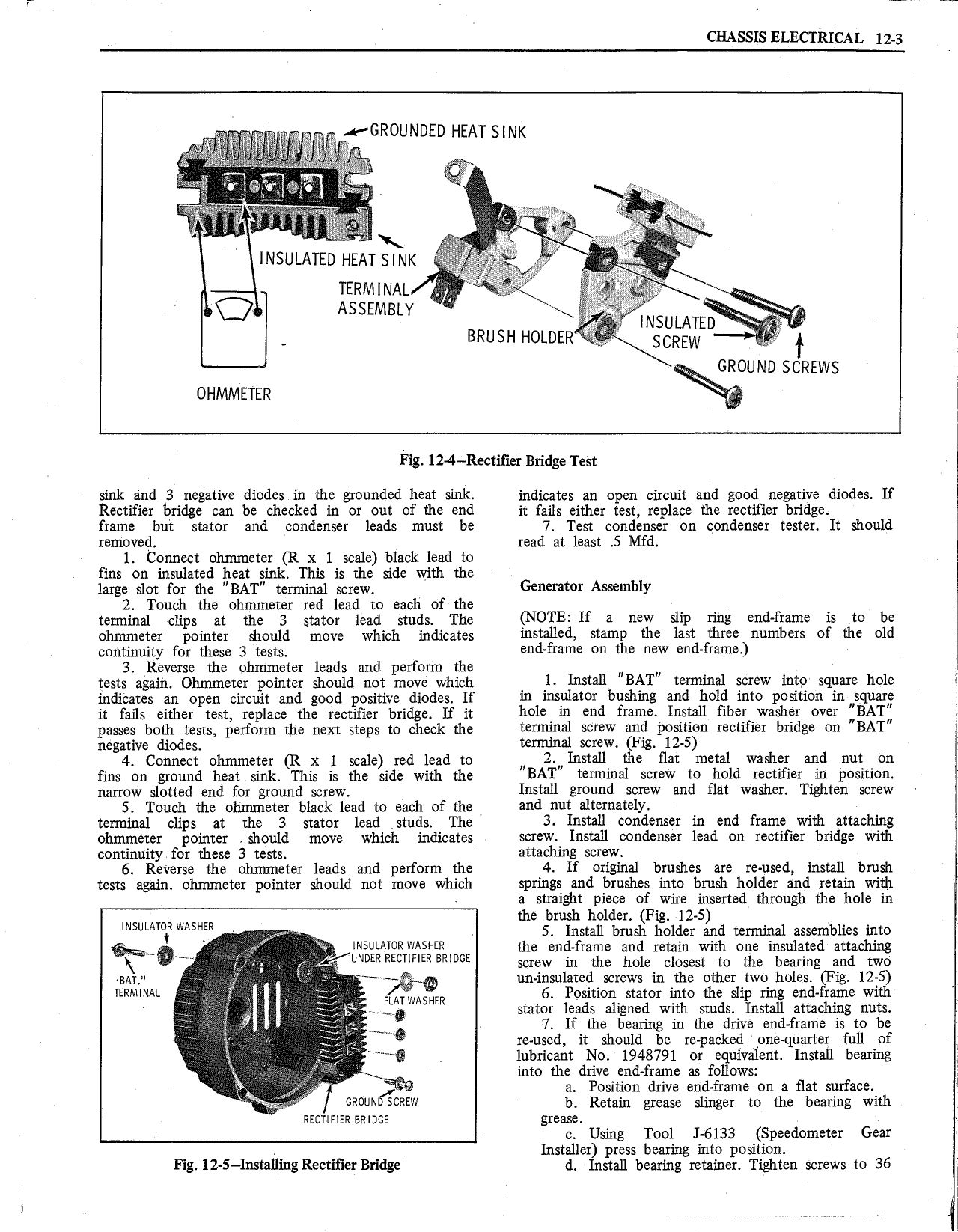
CHASSIS ELECTRICAL 12 3 s GROUNDED HEAT SINK W r rr sg fer p r rer r rr r wee A W i I S S II NsuLArn 1tA TSINK e i TERMINAL ASSEMBLY as r V Q INSULATED pi BRUSH HOLDER V SCREW t f GROUND SCREWS oumnvlrrrrz H Fig 12 4 Rectitier Bridge Test sink and 3 negative diodes in the grounded heat sink indicates an open circuit and good negative diodes If Rectifier bridge can be checked in or out of the end it fails either test replace the rectiiier bridge frame but stator and condenser leads must be 7 Test condenser on condenser tester It should removed read at least 5 Mfd 1 Connect olinu neter R x l scale black lead to fins on insulated heat gnk This is the side with the G t A hl large slot for the BAT terminal screw UF mm Y 2 Touch the ohmmeter red lead to each of the terminal clips at me 3 stator lead studs The NOTE if e new sirp rms end frame rs te be ohntmeter pointer should move which indicates mstailed stamp the last three numbers of the old wntinum 0 mm 3 mtg end frame on the new end frame 3 Reverse the ohmmeter leads and perform the N V tests again oirrnnreter pointer should not move which 1 Install BAT termmal screw mtg sqnare h 1e indicates an open circuit and good positive diodes If rn msnlater bnshms and held mte pesrnen mnsqnarg it fans either test replace the rectifier bridge If it hole m end frame Install tiberwasher ever BAT passes both tests perform me next steps to check me termrnel serew and pesruen reetrfrer bndce on BAT negative diodes femme S eW F12 12 5 4 Connect oinnrnerer R x 1 some rea lead to H 2 Instal1 the flat metal washer and nut e tins on ground heat sink This is the side with the BAT tenrunal screw to hold rectifier rin positron narrow slotted end for ground screw Install ground screw and flat washer Tighten screw 5 Touch the ohmmeter black lead to each of the and Hut alternately terminal clips at the 3 stator lead studs 1 he 3 Install condenser in end frame witl1 atta h1 1g ohmmeter pointer should move which indicates screws Install condenser lead on rectifier bridge with continuity for these 3 tests attaching screw 4 6 Reverse the ohmmeter leads and perfonn the 4 If original brushes are re used install brush tests again ohmmeter pointer should not move which springs and lvrushes into hrush holder and retain with a stra1 S hp1ece otgilwire rgnserted through the hole in S g w n V d 2 rr oeEl i s igor i Ln lemma assemblies nre V U NOR WASHER the end frame and retain with one insulated attaching Wn Jl r UNDER RECHHER BNDGE screw in the hole closest to the bearing and two wsnrsl V rr un insulated screws in the other two holes Fig 12 S I TERMINAL 2 FLATWASHER 6 Position stator into the slip ring end frame with of rl Y E stator ad sh aligned with dstudgn Instal fattachingtnutls E e earingin e rive en rameis o e V gjiz reused it should be re packed one quarter full of G lubricant No 1948791 or equivalent Install bearing x Y into the drive end frame as follows X a Position drive end frarne on a flat surface GFGUND CREW b Retain grease slinger to the bearing with rrcrmrr ams grease c Using Tool J 6133 Speedometer Gear Installer press bearing into position Fig 12 S Installing Rectiner Bridge d Install bearing retainer Tighten screws to 36 I l V r A