Jeep Parts Wiki | Ford Parts Wiki
Home | Search | Browse
|
Body Service Manual August 1964 |
|
Prev
 Next
Next
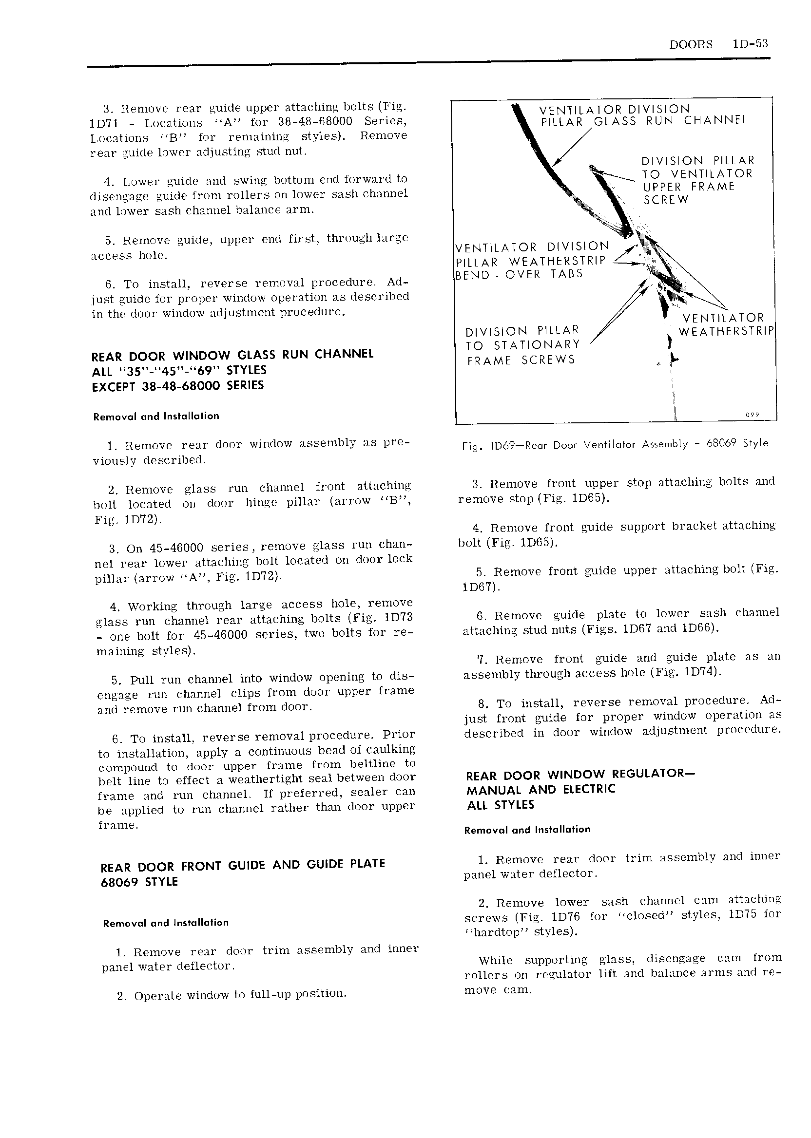
DOORS ID 53 3 Remove rear guide upper attaching bolts Fig 1D7l g Locations A for 38 48 68000 Series ELTL Ag l g5LjO g HANNEL Locations B lor remaining styles Remove rear guide lower adjusting stud nut DIVISION PILLAR 4 Lower guide and swing bottom end forward to R TO VENTILATOR disengage guide from rollers on lower sash channel UPPER FRAME and lower sash channel balance arm SCREW 5 Remove guide upper end first through large J E JCCQSS h j VENTILATOIZ DIVISION PILLAR WEATI IERSTRIP 6 To install reverse removal procedure Ad BEND OVER TABS just guidc for proper window operation as described M in the door window adjustment procedure VENTILATOR DIVISION PILLAR WEATHERSUQIP REAR DOOR w N 0w GLASS RUN cHANNEL IO lAl ONARY l Au ss 4s 69 srYu2s FRAME SCREWS E EXCEPT 38 48 68000 SERIES Remvqn uma nn u a f Il Remove rear door window assembly as pre Fig D69 RE Cr DON Vgnmmor Ais mbly 58060 SME viously described 2 Remove glass run channel front attaching Remove front upper stop attaching bolts and bolt located on door hinge pillar arrow B remove stop Fig 1DG5 Fig lD 72 4 Remove front guide support bracket attaching 3 On 45 46000 series remove glass run chan bolt Fig 1D65 nel rear lower attaching bolt located on door lock pillar arrow A Fig 1D72 5 Remove front guide upper attaching bolt Fig 11367 4 Working through large access hole remove glass run channel rear attaching bolts Fig 1D73 6 Remove guide plate to lower sash channel one bolt for 45 45000 series two bolts for re attaching stud nuts Figs lDG7 and lDG6 maining styles 7 Remove front guide and guide plate as an 5 Pull run channel into window opening to dis assembly through access hole Fig ID74 engage run channel clips from door upper frame and remove run channel from door B To install reverse removal procedure Ad just front guide for proper window operation as 6 To install 1 eV l S 1 mO Hl 1 0 l 11 9 Pl l01 described in door window adjustment procedure to installation apply a continuous bead of caulking compound to door upper frame from beltline to belt line to effect a weathertight seal between door REAR DOOR WINDOW REGULATOR frame and run channel If preferred sealer can MANUAL AND ELECTRIC be applied to run channel rather than door upper ALL STYLES frame Remavul cmd Ins II i n REAR DQQR FRONT GU DE AND GUIDE PLATE 1 Remove rear door trim assembly and inner 68069 STYLE panel water defleetor 2 Remove lower sash channel cam attaching Rem v I nd1 s II i n screws Fig 1D76 for closed styles 1D75 for hardtop styles 1 Remove rear door trim assembly and inner panel water deflector While supporting glass disengage cam from rollers on regulator lift and balance arms and re 2 Operate window to full up position move cam