Jeep Parts Wiki | Ford Parts Wiki
Home | Search | Browse
|
Body Service Manual August 1964 |
|
Prev

 Next
Next
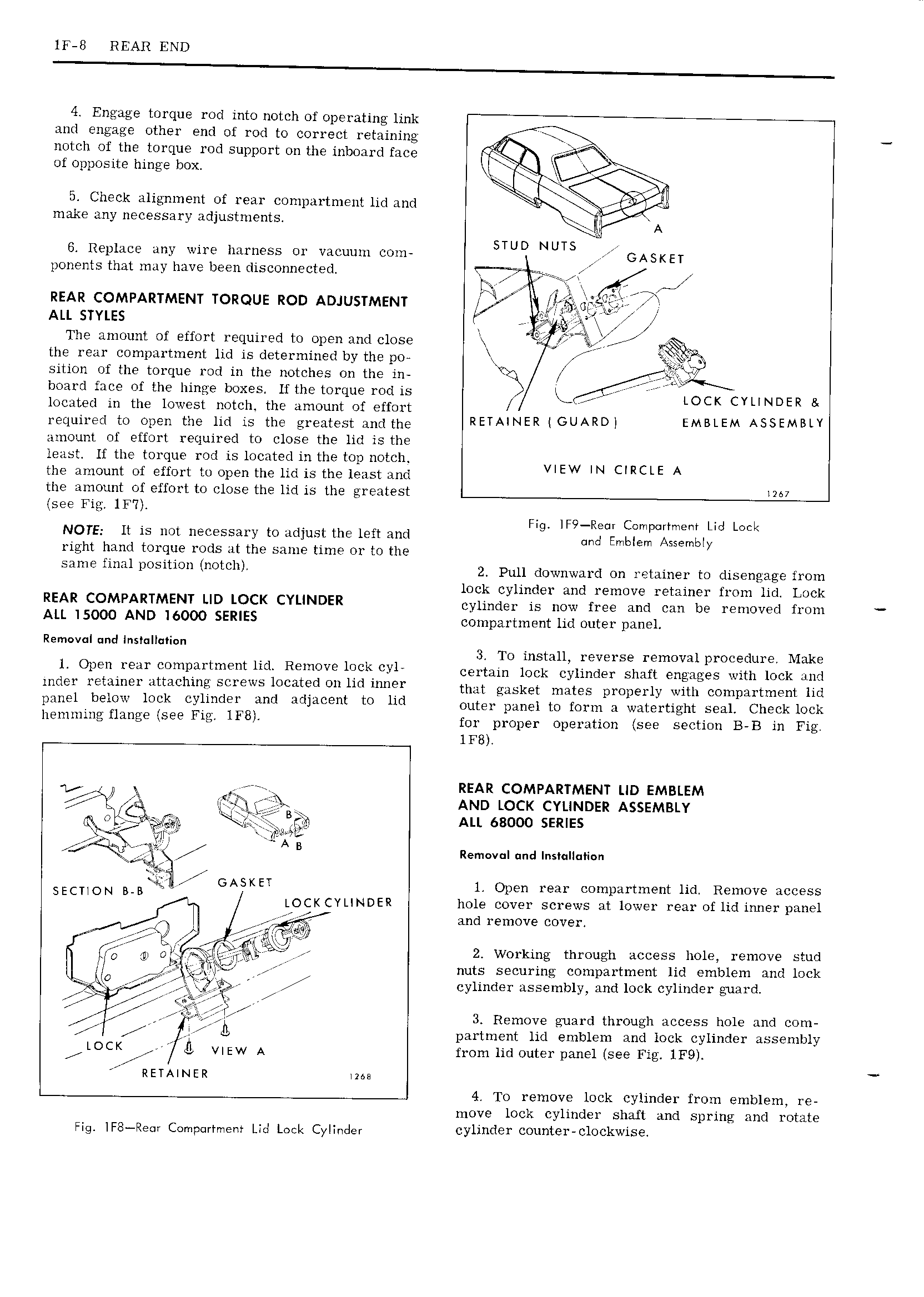
lF 8 REAR END 4 Engage torque rod into notch of operating link and engage other end of rod to correct retaining notch of the torque rod support on the inboard face l TV of opposite hinge box V V 5 Check alignment of rear compartment lid and V make any necessary adjustments lll V A 4 V V STUD NUTS 6 Replace any wire harness or vacuum com GASKET ponents that may have been disconnected l je ey rt REAR COMPARTMENT TORQUE ROD ADJUSTMENT lr wl ALL STYLES tj 5 TT V The amount of effort required to open and close L V jEV ViisVV r V V V g Z the rear compartment lid is determined by the po s rl xkjiy sition of the torque rod in the notches on the in Y V board face of the hinge boxes lf the torque rod is LM VV LOCK CYLINDER Bl located in the lowest notch the amount of effort V required to open the lid is the greatest andthe RETAINER GUARD EMBLEM ASSEMBLY amount of effort required to close the lid is the least If the tor ue rod is located in the top notch the amount of egort to open the lid is the least and VIEW IN CIRCLE A the amount of effort to close the lid is the greatest 2 7 see 1F Fig lF9 Re r Compartment Lid Lock NOTE It is not necessary to adjust the left and and Emblem Assembly right hand torque rods at the same time or to the Same fi 11 Siti t 0t h 2 pun rmwnwar ri tm retainer to rusengage from lock cylinder and remove retainer from lid Lock REAR COMPARTMENT LID LOCK CYLINDER cylinder is now free and can be removed from ALL l5000 AND I6000 SERIES compartment lid outer panel Removal and Installation 3 To install reverse removal procedure Make 1 Open rear compartment lid Remove lock cyl Cermln lock Cylinder Shall engages wml lnck dsml mder retainer attaching screws located on lid inner that msk l males pl 0p l ly will Comparlmenl lld panel below lock cylinder and adjacent to lid Oulu panel to form J watertight Seal Check lock l1P1 i U Q S Fi IFB for proper operation see section B B in Fig lF8 l VA ll l s 7 rrrrrr REAR COMPARTMENT LID EMBLEM i X AND LOCK CYLINDER ASSEMBLY i ALL 68000 semes iii vii rfb VVVVV EIlR I A B Removal und Installation SECUON B B il YR E GASKET l Open rear compartment lid Remove access LOCK CYLINDER hole cover screws at lower rear of lid inner panel Bild remove cove ll l 2 Working through access hole remove stud ll Iil s l 2 nuts securing compartment lid emblem and lock wesgsisc fVll cylinder assembly and lock cylinder guard EV F V VE 3 Remove guard through access hole and com V A 1 V C4 partment lid emblem and lock cylinder assembly LOCK VIEW A from lid outer panel see Fig 1F9 RETAINER ima V 4 To remove lock cylinder from emblem re move lock cylinder shaft and spring and rotate Fig lF8 Re r Campurtmerit Lid Lock Cylinder cylinder counter clockwise

 Next
Next